The correct selection and erection of a wiring system is important to ensure that it is suitable for its intended purpose throughout its lifetime. This article will consider external influences that steel conduit wiring system may be subjected to.
All electrical installations are subject to some form of external influence. It is important, therefore, when selecting a wiring system that all possible detrimental effects are considered.
For steel conduit installations where there may be corrosive or polluting substances present and are likely to cause corrosion or deterioration of the conduit system, then those parts that could be affected must be suitably protected or manufactured from a material that is resistant to such substances. This might mean that during the erection of the conduit system, protective paints or grease have to be applied to protect the conduit from any corrosion or deterioration.
A steel conduit installation forms a robust wiring system, and it has the added benefit that the steel casing will usually satisfy the requirements of a circuit protective conductor.
Where an existing steel conduit system is used as the circuit protective conductor, it will be necessary to verify its suitability for continued use when carrying out periodic inspection and testing on the installation.
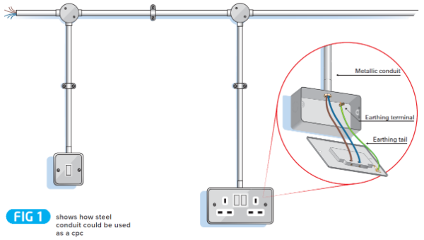
The principal requirements of BS 7671 relating to the use of steel conduit as a circuit protective conductor (cpc) are given in Regulations 543.2.5, and 543.3.6. A typical example is given in Fig 1.
A rigid steel conduit system will generally meet these requirements, for use as the cpc for the circuits it contains, provided that:
- the conduit and associated fittings comply with BS EN 61386- 1: 2008 Conduit systems for cable management. (The original csa of rigid steel conduit can be expected to be sufficient to meet the relevant requirement of BS 7671, which is given in indent (ii) of Regulation 543.2.2, referred to in Regulation 543.2.5)
- the conduit system was properly installed and is in good condition, that is, the conduit is not damaged or deteriorated so as to impair safety, and that there are no installation defects and departures from the requirements of BS 7671 that may give rise to danger (Regulation 621.2 refers),
- the joints in the conduit are mechanically and electrically continuous (Regulation 543.3.6 refers),
- the earthing terminal of each accessory is connected by a separate protective conductor to an earthing terminal in the associated box or other enclosure as shown in Fig 1 (Regulation 543.2.7 refers).

The conduit system should be inspected along its length, as far as practicable, to check the above points.
Particular attention should be paid to checking that there is no significant corrosion such as that shown in Fig 2. It is necessary to verify that no other deterioration that could impair the electrical continuity of the conduit or reduce its csa exists such that it may be unsuitable to carry fault current, and that the joints are not loose. Such deterioration, as shown in Fig 2, may impair electrical continuity, allow ingress of water (or condensation) and/or reduce impact protection to cables within the conduit.
Where the wiring system is buried in the fabric of the building, cover the earth fault loop impedance of all circuits using conduit as their protective conductor is sufficiently low to meet the requirements of BS 7671 for fault protection.
When testing wiring systems that incorporate a steel enclosure, there are three different methods that can be used to verify the integrity of steel enclosure when being used as a circuit protective conductor.
- Using a standard low reading ohmmeter and applying the wandering lead approach as identified by Method 2. This is a low current test which may not exploit any high resistance joints in the steel enclosure. Following this test, the conductor should be inspected along its length to note if there are any obvious points where problems could occur.
- Performing a phase-earth loop impedance test using the line conductor of the circuit in question which forms part of the loop. The measured value obtained would be checked for compliance using the appropriate tables in BS 7671.
- Using an a.c. ohmmeter. This is a high current test using 1.5 times the circuit design current up to a maximum of 25 A.
Special care needs to be taken with this test method as the steel enclosure would be live for the duration of the test. For this reason, this option is not usually selected for premises that are occupied.
For other guidance and publications please see the ELECSA website. Information about the ELECSA Domestic Installers schemes, visit www.elecsa.co.uk