
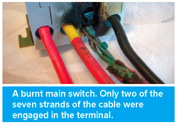
One of the major causes of fire in an electrical installation are either inadequate termination of conductors or the failure of terminations over time. BS 7671 contains requirements intended to protect against the dangers which may arise from poorly constructed electrical connections.
Proper construction
BS 7671 requires every electrical joint and connection to be of proper construction as regards conductance, insulation, mechanical strength and protection. (Regulation 134.1.4). The requirement for proper connections is re-stated and further developed in Section 526. Every connection between conductors and between a conductor and other equipment (such as switchgear, accessories and current-using equipment) is required to provide durable electrical continuity and adequate mechanical strength (Regulation 526.1). Furthermore, the means of connection must take account of the number and shape of the wires forming the conductor (Regulation 526.2). Also, every connection in a live conductor or combined protective and neutral (PEN) conductor must be enclosed and, with few exceptions, connections must be accessible for inspection, testing and maintenance (Regulation 526.3).
Forms of connection
A means of connection between conductors, or between a conductor and an item of other equipment, may take one of many forms, depending on the requirements of a particular installation. Examples of means of connection include a terminal of an accessory or item of switchgear, a terminal of a joint box, a connector block, a soldered joint, a compression-type ferrule, and a soldered or compression type lug bolted to a busbar. Whatever the form of the means of connection, Regulation 526.2 requires its selection to take account, as appropriate, of all of the following characteristics:
Material of the conductor
Precautions must be taken where certain dissimilar metals are placed in contact with each other in the presence of moisture. An aluminium conductor should not be placed in contact with a terminal of brass or other metal having a high copper content, unless the terminal is suitably plated (with zinc or cadmium, for example) or other suitable precautions are taken to prevent corrosion (such as fitting a suitable ferrule to the conductor). Where an aluminium conductor and a copper conductor are joined together, precautions (such as plating) must be taken against corrosion. Where an aluminium conductor is to be connected to a terminal, ferrule or lug, precautions must be taken to ensure that no undue mechanical pressure can be applied to the conductor, for example by the over-tightening of a clamping screw.
Crimped ferrules or lugs should always be those intended for the particular conductor size and shape, and should be compressed only with the dies and nests recommended by the manufacturer of the crimping equipment as being suitable for the particular lug or ferrules and the conductor. Where moisture is likely to adversely affect a connection or joint, effective means of preventing the ingress of such moisture must be provided by, for example, a suitable enclosure or the application of a non-porous wrap-round tape or other proprietary material.
Conductor insulation
Conductor insulation must not be subjected to temperatures exceeding its rated value in normal service. Particular attention is needed where conductors insulated with materials of different temperature ratings, such as thermoplastic (pvc) and thermosetting (XLPE or rubber), are to be connected together. For example, the rated temperature of the insulation at the joint must be not less than the highest of those for the conductor insulation, or the conductors must be sized such that their normal operating temperatures will not exceed the lowest rated temperature of any of the insulating materials.
Number and shape of the wires forming the conductor

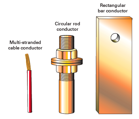
There is a wide range of conductor types which may need to be connected to each other or to other equipment. These include conductors of cables (single stranded, multi-stranded, flexible or nonflexible), braided conductors, circular rods (such as earthing electrodes), and rectangular bars (such as busbars).
Whatever the number or shape of strands (including rods or bars) forming a conductor, the means of connection must be selected so as to securely contain and anchor all the strands of the conductor, make good electrical contact with the conductor, and not damage any of the strands of the conductor in a way likely to impair safety and proper functioning. Where the conductor is shaped (both single or multi-strand), the appropriate matching shaped conductor lug must be selected and used.
The cross-sectional area of the conductor
The means of connection must be suitable for the cross-sectional area (csa) of the conductor such that the conductor can be inserted into the terminal or other means of connection without using excessive force. Good electrical contact must be provided between the conductor and the means of connection. For example, the terminal or other means of connection must be neither too large nor too small for the conductor, and must be correctly designed for the shape of the conductor.
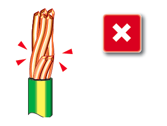
Adequate mechanical strength must be provided by the means of connection to allow for movement during normal and fault conditions. Where it is necessary to reduce the csa, or change the shape of a conductor at the point of connection, this should be achieved by means of a recognised technique, such as the use of an appropriate pin connector. It is not acceptable to cut one or more strands from a stranded conductor in order to engage it into a smaller terminal.
Number of conductors to be connected together
BS 7671 does not place a particular limit on the number of conductors that an individual terminal or other means of connection may be used to connect together, provided the requirements relating to proper construction are met. However, the number of conductors must be limited where necessary to facilitate the proper identification, inspection, testing and maintenance of the connections or conductors (Regulations 514.1.2 and 513.1).
Temperature attained by terminals
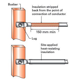
The temperature attained by terminals in normal service must be such that the effectiveness of the insulation of the conductors connected to them is not impaired. For most types of equipment, the temperature attained by terminals in normal service is unlikely to impair the effectiveness of the insulation of the conductors connected to them. However, consider an example of a busbar rated for a maximum operating temperature of 90ºC. Where a conductor insulated with a material rated for a normal operating temperature of 70ºC (such as 70ºC thermoplastic (pvc)) is to be connected to a busbar intended to operate at above that temperature, the conductor insulation should be suitable for the maximum temperature of the bare conductor or busbar. This may require the stripping of the pvc insulation and the application of a higher temperature rated insulating material to the cable (Regulation 526.4). The terminations of mineral insulated cables at busbars rated to operate at higher temperatures must be fitted with sleeves and seals having a suitable temperature rating, obtained from the cable manufacturer.
Soldered connections
Where a soldered connection is to be used, the design must take account of creep (‘cold flow’), mechanical stress and temperature rise under fault conditions. Soldering of lugs and ferrules to conductors, although rarely carried out nowadays, was common practice until the use of compression-type sockets became established in the 1960s. In the absence of more precise information, soldered connections or joints are limited to a maximum temperature under fault conditions of 160ºC. They are therefore unsuitable for cable installations taking full advantage of the limiting final temperatures above 160ºC offered by cables insulated with certain materials (such as thermosetting material). It is worth noting that the fitting and soldering of lugs and ferrules is a skilled practice and therefore relies on a jointer’s skill to produce a solid ferrule or lug without leaving cavities or poorly tinned conductor strands. Such defects can result in a high resistance connection, leading to premature failure.
Locking arrangements
Adequate locking arrangements must be provided in situations subject to vibration or thermal cycling. Locknuts or other suitable locking arrangements must be provided to prevent terminal screws or other means of connection becoming loose in service where subject to such conditions.
Checking that a cable connection is soundly made
When constructing, or prior to energising, a new installation or during periodic inspection of an existing installation, it is necessary to check that connections are sound. Different methods may be employed including one or all of:
- Visual inspection of the joint to check that all the strands are engaged and that there are no signs of overheating
- Gently pulling on the conductor to check it is not loose in the terminal
- Checking the screw or bolt is tight with a screwdriver, spanner or other tool
- Checking low resistance/continuity with an instrument.
For other guidance and publications please see the ELECSA website.