Published: 11 July 2013
Category: Technical articles
Using the results from measuring (R1+R2) and Ze is preferable to carrying out direct measurements of earth fault loop impedance to determine Zs values for a final circuit such as a lighting circuit.

Direct measurement of earth fault loop impedance on final circuits may involve unnecessary working on or near live parts.
1. Direct measurement of Zs using an earth fault loop impedance test instrument.
2. Adding the result of the value of external earth fault loop impedance (Ze) to the measured value of (R1 + R2) at the end of the circuit.
NICEIC considers that the second method is the more suitable for lighting circuits. This method is explained in more detail below.
Measurement of Ze
Regulation 313.1 requires the value of Ze to be determined for every installation. Measurement of Ze necessarily involves the working on or near live parts. However, this needs to be done only once during initial verification of the installation and once during each subsequent periodic inspection.
Measurement of (R1 + R2)
The purpose of measuring (R1 + R2) for a circuit is to:
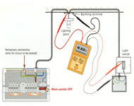
- Obtain the ohmic value of (R1 + R2) at the electrically most distant point or accessory of the circuit from the distribution board, for entering in the schedule of test results.
- Confirm continuity of the circuit protective conductor to each point and accessory, and
- Check correct polarity at each point and accessory.
Values of (R1 + R2) are measured using a ohmmeter with a low range, such as 0 to 20 Ω, having a no-load voltage of between 4 V and 24 V d.c. or a.c., and a short-circuit current of not less than 200 mA (Regulation 612.2.1 refers)
Determining the measured value of Zs from the results of Ze and (R1 + R2) tests
The value of Zs for a given circuit is calculated from the formula:
Zs = Ze + (R1 + R2) furthest Ω
Where:
Ze is the measured value of external earth fault loop impedance in ohms
(R1 + R2) furthest is the value in (R1 + R2) in ohms measured at the electrically most distant point or accessory from the distribution board (or consumer unit).
If the distribution board (or consumer unit) supplying the circuit is not at the origin of the installation, the above formula is modified to:
Zs = Zdb + (R1 + R2) furthest Ω
Where:
Zdb is the value of earth fault loop impedance in ohms measured at the distribution board or consumer unit.
(iv) The earth fault loop impedance of that part of the system external to the installation Ze.
Solution
The measurement of earth fault loop impedance (Zs) for a final circuit such as a lighting circuit can be determined by one of two methods:1. Direct measurement of Zs using an earth fault loop impedance test instrument.
2. Adding the result of the value of external earth fault loop impedance (Ze) to the measured value of (R1 + R2) at the end of the circuit.
NICEIC considers that the second method is the more suitable for lighting circuits. This method is explained in more detail below.
Measurement of Ze
Regulation 313.1 requires the value of Ze to be determined for every installation. Measurement of Ze necessarily involves the working on or near live parts. However, this needs to be done only once during initial verification of the installation and once during each subsequent periodic inspection.
Measurement of (R1 + R2)
The purpose of measuring (R1 + R2) for a circuit is to:
- Obtain the ohmic value of (R1 + R2) at the electrically most distant point or accessory of the circuit from the distribution board, for entering in the schedule of test results.
- Confirm continuity of the circuit protective conductor to each point and accessory, and
- Check correct polarity at each point and accessory.
Values of (R1 + R2) are measured using a ohmmeter with a low range, such as 0 to 20 Ω, having a no-load voltage of between 4 V and 24 V d.c. or a.c., and a short-circuit current of not less than 200 mA (Regulation 612.2.1 refers)
Determining the measured value of Zs from the results of Ze and (R1 + R2) tests
The value of Zs for a given circuit is calculated from the formula:
Zs = Ze + (R1 + R2) furthest Ω
Where:
Ze is the measured value of external earth fault loop impedance in ohms
(R1 + R2) furthest is the value in (R1 + R2) in ohms measured at the electrically most distant point or accessory from the distribution board (or consumer unit).
If the distribution board (or consumer unit) supplying the circuit is not at the origin of the installation, the above formula is modified to:
Zs = Zdb + (R1 + R2) furthest Ω
Where:
Zdb is the value of earth fault loop impedance in ohms measured at the distribution board or consumer unit.
Regulation 313.1 (part of)
The following characteristics of the supply or supplies, from whatever source, and the normal range of those characteristics where appropriate, shall be determined by calculation, measurement or enquiry or inspection:(iv) The earth fault loop impedance of that part of the system external to the installation Ze.
Regulation 612.2.1
A continuity test shall be made. It is recommended that the test be carried out with a supply having a no-load voltage between 4V and 24 V, d.c. or a.c., and a short-circuit current of not less than 200 mA.This article is extracted from Snags and Solutions Part 3 – Inspection and testing- published by NICEIC. Copies of this book are available here