This article discusses the factors that a contractor should consider when installing an electric boiler.

As it is becoming more commonplace for electric boilers to be installed as the heat source for wet central heating systems in domestic and similar premises, this article discusses the factors that a contractor should consider when installing an electrical boiler.
Capacity of main incoming electricity supply
The addition of an electrical boiler, typically in the range of 6 kW to 12 kW, to a 230 V single-phase installation is likely to significantly increase the maximum demand of the installation. For example, the installation of a 10 kW electric boiler will result in an additional current demand of approximately 44 A. Considering the supply rating for many domestic premises, especially rural premises supplied by overhead lines, may only be 60 A, then once the boiler is in operation there will be limited capacity to meet the demand for all the other loads.
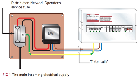
In view of this, an assessment of the main incoming electrical supply must be made to verify that sufficient capacity is available to accommodate the installation of an electric boiler (Regulation 313.1 of BS 7671 refers). The assessment should include the rating of the cut-out, meter and the ‘meter tails’ (Fig 1 refers).
Where the incoming supply is considered to be of insufficient capacity to accommodate the additional (electric boiler) load, the Distribution Network Operator should be contacted so that arrangements can be made for a larger supply to be connected.
Depending on the position of the service connection to the network and/or costs involved a larger supply may not be practicable; hence it is necessary to assess the capacity of the incoming supply before any boiler or installation costs have been incurred.

Final circuit arrangement
Having determined the supply is adequate to meet the additional demand, a method for connection of the final circuit should be determined. There are typically two methods used to connect a final circuit:
1. To a protective device in the consumer unit (Fig 1), or
2. To an individual switch fused (or circuit-breaker) mounted separately (Fig 2).
While both methods are standard installation practice; due to the size of cable (see later) associated with the load of an electric boiler, Method 2 (refer to Fig 2) is more appropriate for an existing installation where:
- the existing consumer unit cannot accommodate the connection of a final circuit for an electric boiler, due to an inadequately rated main switch (such as 60 A), and/or
- the terminals within the unit do not accommodate large conductors, such as 10 mm² or greater, and/or
- the boiler has a rating of 12 kW (current rating about 52 A); meaning a protective device of 60/63 A is required (certain manufacturers do not provide or recommend protective devices greater than 50 A for their consumer units).
Final circuit wiring
In domestic and similar premises contractors normally select insulated and sheathed flat cable and apply Table 4D5 of BS 7671 to determine the cross-sectional area of the live conductors.
For an electric boiler, a cable having live conductors larger than that generally associated with final circuits in domestic and similar premises may be required. For example, where to heat the premises a boiler having a rating of 10 kW (about 44 A) is required, and the method of installation is Method 101, a cable having live conductors of 16 mm2 will be required (Table 4D5 refers).
Conductors should be sized in accordance with the relevant parts of Chapter 52 and Appendix 4 of BS 7671. The earthing and bonding conductors should meet the applicable requirements of Chapter 54 (Earthing arrangements and protective conductors). Furthermore, cables installed in walls and partitions will also need to comply with Regulation Group 522.6.
Overcurrent protective device
The overcurrent protective device for the final circuit should be selected in accordance with the relevant parts of Chapter 43 of BS 7671. However, the manufacturer’s instructions should also be taken into account. For example, typically in domestic and similar premises circuit-breakers to BS EN 60898 Type B are the contractors preferred choice, however, manufacturer’s instructions may specify a Type C device to minimise unwanted tripping during the boiler switching cycles.

Isolation
Regulation 537.2.2.6 requires an isolating device to be clearly identified by position or durable marking to indicate the installation or circuit it isolates. For the installation shown in Fig 1 the means of isolation is self-explanatory; however, for the installation shown in Fig 2 there are two main switches, and to ensure correct isolation and the subsequent safety of persons, adequate identification and notices will be required to clearly identify the particular parts of the installation controlled by each main switch: a warning notice (as illustrated in Fig 3) may be used to avoid confusion.
For other guidance and publications please see the NICEIC website. For information about the NICEIC Approved Contractor or Domestic Installers schemes, visit www.niceic.com
