
This article provides information on conventional arrangements for radial final circuits for cookers in household premises.
A cooker control unit is an assembly primarily intended for controlling the supply of electricity to a cooker. It also incorporates a switched socket-outlet for the electrical supply to other electrical appliances. The product standard for cooker control units is BS 4177:1992 - Specification for cooker control units.
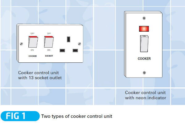
Cooker control unit
Cooker control units designed to BS 4177 have a rated voltage not exceeding 250 V a.c. The switch controlling the supply to the cooker has a rated current of either 32 A or 45 A, and the switched socket-outlet has a rated current of either 13 A (BS 1363 type) or 15 A (BS 546 type).
Cooker control units are available for surface mounting, flush mounting or panel mounting, and may or may not be fitted with a luminous indicator, such as a neon lamp, to indicate that the circuit is energised as shown in Fig 1.
Installation
Where the mounting box is not part of the accessory, such as may be the case with a flush wall-mounted cooker control unit, the mounting box will need to be chosen so that it affords ample space for the connections and the conductors, bearing in mind the size of the cable to be used. Guidance on the required depth of accessory box is generally provided by the manufacturer of the cooker control unit.
A cooker control unit needs to be accessible to the user, but should not be positioned such that the user has to reach across the cooker hob to gain access to the unit. Similarly, it should not be positioned where the flexible cable from the socket-outlet may come into contact with hot surfaces or dislodge items cooking on the hob. Furthermore, the unit should be accessible if there was a cooker fire.

Final connection
As for all final connections to items of current-using equipment; the final connection to a cooker should be made in such a way that stress and strain on connections is avoided, as required by Regulation 522.8.5. One method of complying with the requirements of Regulation 522.8.5 is to make the final connection to the cooker via a cooker connection unit to BS 5733 as shown in Fig 2.
Conventional arrangements for radial final circuits for cookers
Each cooker should be supplied by a radial final circuit dedicated for the purpose, and should be connected to the final circuit by a readily accessible means of interrupting the supply on-load (see Fig 1). For the purposes of this topic a cooker is a hob unit, an oven/grill or a combination of both.
One dedicated circuit of suitable rating may be used to supply two or more cookers, an oven/grill and a separate hob unit for example, where they are installed in the same room. In such cases, the cookers may be connected to the final circuit either individually by means of a cooker control switch or cooker control unit, or collectively by means of one such unit common to all the cookers (see Fig 3).
The means of interrupting the supply on load should be readily accessible but the device should not be positioned where, in order to access it, a person would have to reach over the cooking appliances. Consideration should also be given as to whether the position of the device enables it to remain readily accessible in the event of a cooking fire.
The current rating of a cooker final circuit is determined by an assessment of the current demand of the cooking appliances and, if a cooker control unit is provided, the current demand of the socket-outlet. A 30/32 ampere circuit is generally suitable for most household cookers (4 heating rings, a grill and an oven) but a circuit of higher current rating may be necessary for cookers having additional cooking facilities and/or larger capacity ovens.
When determining the current rating required for a final circuit supplying one or more cookers, consideration should be given to the discrimination requirements of Regulation 536.1. The Regulation requires the characteristics and setting of an overcurrent protective device to be such that any intended discrimination is achieved where necessary to prevent danger. If the rated current (In) of the overcurrent protective device for the circuit supplying a cooker is too high, discrimination with the overcurrent protective device upstream (such as the electricity distributor’s fuse) may not be achieved.
As for any other circuit, the voltage drop between the origin of the installation and the terminals of the cooker needs to be checked in order to verify compliance with Section 525 of BS 7671.
For other guidance and publications please see the ELECSA website. Information about the ELECSA Domestic Installers schemes, visit www.elecsa.co.uk