Why do cooker switches and cooker control units have different standards?

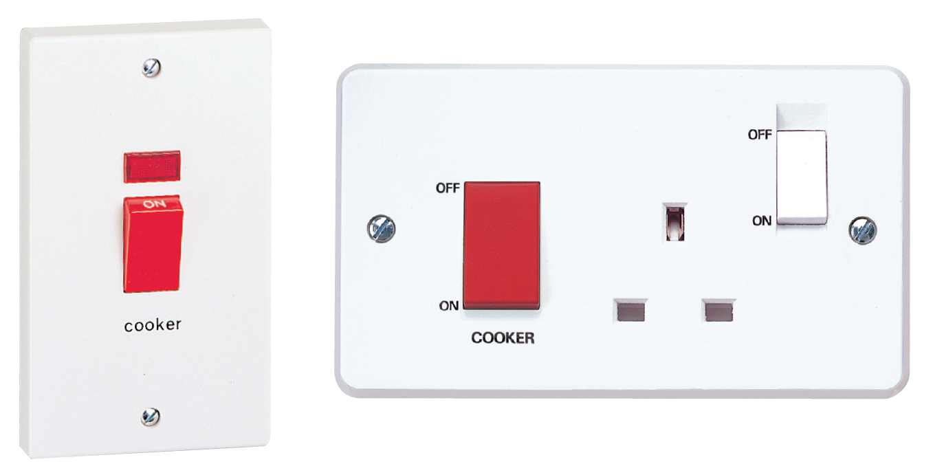
The installation of cooker switches or cooker control units is a useful alternative to the electrical installation of a cooking appliance via a plug and socket-outlet. For cooker switches, they must comply with BS EN 60669-2-4[1], and for cooker control units the applicable standard is BS 4177[2].
Why the different standards?
A switch used for the control of a cooker that does not comply with Parts 2-4 of the BS EN 60669 series is not suitable for isolation purposes. It would only be suitable for emergency switching and functional purposes (Table 537.4 of BS 7671 refers).
A cooker control unit complying with BS 4177 incorporates a cooker control unit switch and a socket-outlet, and the switch on this unit is an isolator. This means the device is suitable for on-load isolation, that is, disconnection whilst carrying load current.
Function of a cooker control unit
The cooker switch/control unit is often used to serve the following functions in respect of the cooking appliance.
• A means of isolation (Regulation Group 537.2), such as to facilitate electrical connection or repair of the appliance without having to isolate at the consumer unit or distribution board
• A means of switching off for mechanical maintenance (Regulation Group 537.3), such as to avoid the risk of burns or mechanical injury (from an oven fan, for example) as a result of a switch on the appliance being accidentally turned on during cleaning or mechanical repair of the appliance
A current rating of 30 or 32 A at 230 V single-phase is generally suitable for a cooker switch/control unit (and the associated dedicated final circuit) supplying most household cookers – which typically have four heating rings, a grill, and an oven. However, a higher current rating may be necessary for a cooker having additional cooking facilities and/or a large capacity oven.
An assessment of the likely maximum demand of a household cooker can be made by taking the first 10 A of the rated current, plus 30 % of the remainder of the rated current, plus 5 A for the socket-outlet of a cooker control unit if one is fitted.
A cooker switch/control unit may be used to control two or more cooking appliances in the same room (such as an oven/grill and a separate hob unit), as shown in Fig 1, provided it has sufficient current rating.

Positioning
The switch or control unit should be positioned so that it is accessible and convenient for use. It should not be positioned behind or above a cooking appliance such that a person would have to reach over the appliance in order to access the switch/control unit.
The horizontal distance between a cooker switch/control unit and the appliance(s) it serves must be sufficiently short for the switch to be under the control of persons relying on it for safety. Historically, this requirement was likely to be met if the distance between switch and cooker did not exceed 2 m. This requirement is no longer stipulated in BS 7671; however, good practice would recommend that the means of control is placed locally to the cooking equipment.
The height of a cooker switch or control unit in an installation in a new dwelling should be suitable to facilitate access by persons in wheelchairs and others whose reach is limited (as should the heights of all wall-mounted switches and socket-outlets). Based on the recommendations of Approved Document M, applicable in England and Wales, the height of the switch or control unit should not exceed 1.2 m above floor level (see Fig 2).

A cooker switch or control unit should not be installed in a cupboard or cabinet unless it will be accessible and convenient for use. In any event, wiring and other electrical equipment should not be fixed to any part of a cupboard or cabinet that is demountable in normal use.
It is recommended not to locate a cooker switch or control unit in a central wall mounted control panel together with other switching devices, as this may result in the cooker switch/control unit not being under the control of persons relying on it for safety or otherwise not being suitably accessible.
Where a cooker switch or control unit is positioned in such a central control panel, then, as for any other item of switchgear or controlgear, a label or other suitable means of identification must be provided to indicate the purpose of the cooker switch/control unit, except where there is no possibility of confusion (Regulation 514.1.1 refers).
Particular considerations for cooker control units
The installation of a cooker control unit can lead to accidents due to trailing cables and/or portable equipment being located near to or on hot surfaces. Where a cooker control unit is provided, it should be positioned so as to minimise the risk of such accidents. If this is not practicable, it is better to install a cooker switch (without a socket-outlet), bearing in mind that a modern kitchen installation should have a sufficient number of socket-outlets provided from the dedicated socket-outlet circuits.
Like any other general-purpose socket-outlet, the socket-outlet of a cooker control is subject to the requirement of Regulation 411.3.3 to be provided with additional protection by an RCD. The RCD must have a rated residual operating current (IΔn) not exceeding 30 mA.
An exception is permitted where, other than for an installation in a dwelling, a documented risk assessment determines that RCD protection is not necessary for socket-outlets having a rated current not exceeding 32 A.
However, if the circuit cable supplying the cooker control unit or cooker switch is concealed in a wall or partition, additional protection by an RCD is likely to be required in any case by Regulation 522.6.202 or 522.6.204, except where these regulations make it clear that such protection is not required (such as where the cable is enclosed in earthed metal conduit).
[2] BS 4177: 1992 - Specification for cooker control units.