Chaz Andrews Doepke Technical Manager – Outlines key points and selection possibilities when connecting RCDs in series for EV installations.

EV charging circuits requiring two or more RCDs in series should provide for selectivity between RCDs under residual current fault conditions. The Site survey, physical layout, design, positioning of the circuits, types of cable and location of the RCDs within the circuits will determine if this is actually possible.
722 Amendment 1 – Design Rules
The IET Code of Practice EV Charging Equipment Installations 4th Edition (CoP), gives detailed design requirements. Effective and safe design solutions for a specific installation relies on the correct interpretation of the rules e.g. 722.531.3.101 Amd 1 referring to 30 mA RCDs;
“..each charging point ….. shall be protected by….” It does not state that the RCD must be in the chargepoint – see Note 3.
In Domestic installation with a single Mode 3 charge point, if the design requires a 30mA RCD upstream (see CoP clause 5.6.2), an additional RCD in the chargepoint adds to the operational complexity. However this does not apply to V2G or V2H installations if the vehicle is providing storage – see CoP section 10. A supply cable with the potential to be fed from either end may require two RCDs, based on vehicle to grid / grid to vehicle operating mode, possible location of the fault and the installation rules requiring RCD protection.
Consider the rules carefully, before making a decision on the final design of the installation.
Different Types of RCD in series
722.531.3.101 Amd. 1 Note 1 refers to Regulation 531.3.3; detailing the requirements for selecting Types of RCD, based on the nature of the residual currents.
In Fig 1, the upstream RCD will be subjected to the combined residual currents. In this example iFDC would exceed 6 mA up to 12 mA, before one of the chargepoints outputs is switched off.
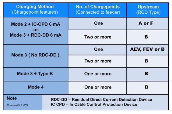
To meet BS 7671 531.3.3 a Type B RCD is required upstream of two or more chargepoints, as the combined d.c. leakage current can exceed the safe limit specified in the Regulations for the use of Type A / F RCDs – see Fig 2.
Fig 2 details the requirements for the upstream RCD, based on BS7671 722.531.3.101 Note 1 and Regulation 531.3.3; the charging mode, chargepoint design, Type of RCD and N° of chargepoints connected to the feeder circuits containing upstream RCDs.
Selectivity
In addition to the RCD Type, selectivity must be considered when installing RCDs in series, specifically with regard to the continuity of supply to other RCD protected services. See CoP Fig 8.1 chargepoints located inside and 8.2 for chargepoints located outside, with the upstream RCD providing fault protection - see BS7671 411.3.2
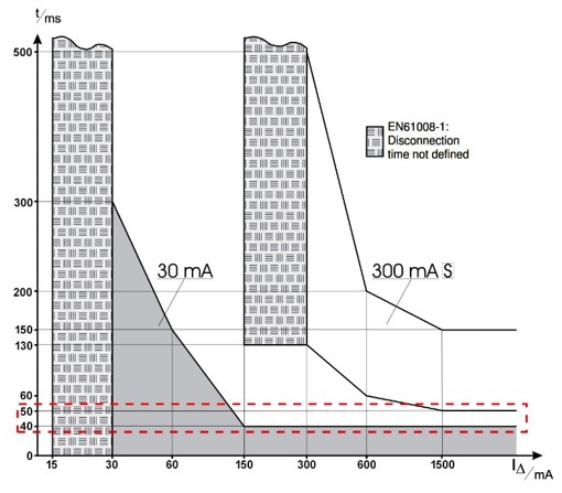
The product standard BS EN 61008-1 Table 1 specifies a minimum non actuating time of 50 ms* for Selective RCCBs. This is represented graphically in Fig 3; comparing 30 mA general delay and 300 mA selective delay RCCB characteristics.
The 10 ms difference (50-40) is required to achieve full selectivity. Using 100 mA , 100 mA “S” or 300 mA upstream of 30 mA may only achieve partial selectivity under certain residual current fault conditions.
*Note: BS7671 Appendix 3 Table 3A; minimum tripping time for Selective RCDs at 5I∆n (40 ms), would not provide discrimination with the maximum tripping time allowed for a 30 mA RCD at 5I∆n.
Conclusion
Check the EV Manufacturer’s chargepoint specification for specific RCD requirements and any additional equipment requirements to meet BS7671. For smaller installations containing multiple chargepoints, it may be cost effective to consider a design using individual feeder circuits with separate RCDs for each charge point. For more complex installations with existing RCD protection on the main incoming supply, consider the design carefully e.g. RCDs, Type and sensitivity already installed, selectivity, possibilities for separate supply etc. Refer to the revised Code of Practice for EV Charging Equipment Installations 4th Edition; equipment that fails to meet the regulations, will not provide the expected level of protection. For further information please refer to the Doepke Web Site.
Chaz Andrews – Technical Manager, Doepke UK Ltd