A busbar is a device in an electrical power distribution system that conducts electricity within a switchboard, distribution board, substation, other electrical apparatus, or in a building. But why use busbars instead of cable? Voltimum UK Managing Editor James Hunt explains:
Why use busbars instead of cable? While cable is still ideal for most general applications, it is much less suitable for certain high power applications and, in any case, busbars can provide many benefits in use. For example, compared with the equivalent cable system that would otherwise be required, busbars can reduce system costs by decreasing assembly times, and they also improve reliability by reducing or eliminating cabling errors (which also improves quality). Busbars also help increase capacitance, resulting in greater effective signal suppression and noise elimination and further, their use lowers inductance. In particular, laminated busbars can reduce the proximity effect in many semiconductor applications, as well as in applications that involve high electromagnetic interference (EMI). Busbars have yet another benefit in that impedance can also be reduced, so helping to further reduce unwanted noise. Busbars can also provide denser packaging and can be provided, in many cases, with a wide range of connection methods, so adding to flexibility in installation and use. Finally, busbars will withstand high bending forces (up to a point) under fault condition, and will improve thermal characteristics if properly designed.
Busbar features:
Busbars are supported on insulators. Alternatively, they may be completely encapsulated in insulating material, and they are protected against accidental contact either by a metal (or plastics) enclosure or by being out of normal reach. Neutral busbars are also often insulated, while earth busbars are typically bolted directly on to any metal part of an electrical system's enclosure, chassis or building earth.
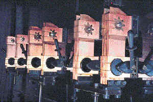
In terms of connection, busbars can be joined to each other, and to electrical equipment, by bolted or clamped connections. It is often the case that joints between high-current busbar sections have carefully matched silver-plated contact surfaces to reduce the contact resistance.
The Copper Development Association (CDA) points out that, where busbars carry voltages of over 300kV outdoors, a corona around the connections can be produced, and this becomes a source of radio-frequency interference (RFI) and power loss. In such circumstances, special connection fittings are necessary.
Busbar design considerations:
Proper sizing is crucial if the busbar is to safely carry the maximum current required. For example, while smaller distribution boards and consumer units may have busbars having a cross sectional area of as little as 10 mm², those in electrical substations may be of 1,000 mm², or even larger.
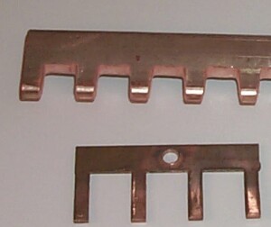
Busbars are nearly always made in flat section bar, for low and medium voltage electrical installations at least, because this shape allows heat to dissipate more efficiently through the high surface area to cross-sectional area ratio. The other busbar shape is of a hollow tube, used for the same reason, but mainly for high voltage/current installations because the shape reduces skin effect and is stiffer. High stiffness is very important where large powers (high currents) are concerned, because of the very high bending forces that may result from a fault condition. Today's electrical generating and distribution plant, and electrically driven industrial plant have high power requirements, and can give rise to very large electromagnetic forces in the electrical installation, especially is a short circuit fault occurs. Busbars must be able to withstand such bending forces without damage, and must be designed to operate within the temperature limits laid down in BS 159, BS EN 60439-1:1994 (or other national or international standards). Heat loss is energy loss, so a low resistance material (and suitable busbar cross-sectional area) is essential to avoid energy loss (and loss of revenue).
Busbar installations and other low voltage assemblies could frequently be designed to a lower rating - with consequent savings in material and cost - if principles similar to those used to design of cable installations in BS 7671, The IEE Wiring Regulations, were also applied to them. So say Ray Upton and Chris Smith of Eaton's MEM. Go to the article entitled 'Are busbar trunking systems over-engineered?' in this VoltiBULLETIN to find out more.
Busbar materials:
Busbars could, in theory, be made of any conducting material. Such a material must have suitable properties for safe, efficient operation of electrical equipment using busbars for current carrying. Such properties are:
- Low electrical and thermal resistance.
- High mechanical strength in tension, compression and shear.
- High fatigue failure resistance.
- Low surface film electrical resistance.
- Simple to make.
- High corrosion resistance.
- Competitive first cost.
- High recycling value.
The material that most closely matches these many properties is copper, though aluminum is also very suitable (and is much lighter), but it is usually copper which, in practice, is used for the majority of busbars because, for conductivity and strength, its high conductivity is superior to that of aluminium. Where lightness is crucial, then aluminium may be the better option, even though its cross-section would have to be larger. Note that aluminium busbars may also need more supports than copper busbars. For higher stresses and/or temperatures, busbars can be made from copper containing about 0.1% of silver. This improves creep and softening resistance. Copper's greater harness means, generally speaking, that fewer problems will occur when clamped joints are used to connect busbar lengths together, and there are other advantages of copper over aluminium. Copper also has a high recovery value.
The current-carrying capacity of a busbar is usually determined by its maximum operating temperature, as defined by national and international standards such as BS 159. This stipulates a maximum temperature rise of 50°C above a 24-hour mean ambient temperature of up to 35°C, and a peak ambient temperature of 40°C.
Busbar applications:
Busbars can be used wherever electricity has to be carried. Most applications are in relatively (or very) heavy current carrying applications, such as in control and distribution panels, or feeder systems and uprisers in buildings, but even consumer units have their own mini-busbars. Busbars are also widely used in certain types of lighting system. For example, lighting busbar (or as busbar trunking, of which more later) is available in 25A and 40A ratings in both 4- and 6-pole variants. Such busbar is used mainly for overhead installation, and is suitable for all types of commercial lighting, and in retail stores, offices and hotels. It can be used to create flexibility in creating specific lighting schemes.
Busbar trunking:
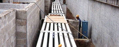
Busbar trunking - essentially busbars contained inside a (normally steel) trunking system - provides the basic infrastructure of an electrical power system. As such today, it is often called 'powertrack'. The first busbar trunking was simply a set of busbars mounted in an elongated busbar chamber. As such, it provided a good alternative to cable, especially in high current applications which, at the time, would have meant using very bulky cables that were difficult to handle.
Modern busbar trunking is generally formed of insulated solid copper or aluminium busbars encased in steel, and have been designed from the outset for installation applications, rather than being merely adaptations of switchboard busbar assembly.
Busbar trunking has a number of benefits over cabling systems, some deriving from the advantages of busbars over relatively inflexible cable; others deriving from the combination of busbars within a properly designed modular containment system. Busbar trunking can be more flexible in terms of changes to the installation some time in the future. It is, in any case, usually quick and easy to install, being supplied in pre-fabricated lengths with accessories and joints such as corner pieces, T-connectors and circuit protection devices that simply plug-in.
In this VoltiTECH, ASTA BEAB's Colin Stephens takes a technical look at the testing of busbar trunking systems. Click on the article entitled 'Testing busbar trunking and powertrack systems'.
In application, busbar trunking systems are often used in underfloor distribution to socket outlets and in ceilings for connection of luminaires, allowing flexibility in final circuit design for redesign of office layouts - see Schneider Electric's Canalis busbar trunking in the article entitled 'Busbar range expanded'.
Schneider Electric's Lynsey Perks analyses in detail the benefits of busbar trunking, and provides contractors with useful guidance on its use in the article entitled 'Busbar trunking - simply a better option' in this VoltiTECH. Legrand says that its range of Arena-Walsall Power Track busbar trunking saves contractors time and money on installation. This and two applications are provided in the article entitled 'Fast-fit power track from Legrand'.