
Prospective fault current (Ipf) is the value of overcurrent that would flow in the event of a short-circuit or an earth fault occurring in an electrical installation. Where protective devices do not have sufficient breaking (and for a circuit-breaker making) capacity to cope safely with such fault currents there is a risk of injury or damage from electrical arcing and even fire.
For these reasons, Regulation 612.11 of BS 7671 requires that the prospective short-circuit current and prospective earth fault current is measured, calculated (or otherwise determined) at the origin and at other relevant points in the installation.
The maximum prospective fault current
The maximum fault current in an installation will occur at that point where the conductors have their lowest value of resistance. Therefore, to obtain a maximum value for the installation the test needs to be conducted at the origin of the installation, such as at the main switch or at other switchgear connected directly to the tails from the electricity distributor’s metering equipment. Where a measurement is made at a point in the installation other than the origin, such as an item of switchgear fed by a distribution circuit, it would not be the maximum value for the installation.
Test precautions
Particular care should be exercised during the testing process, as fault conditions are most severe at the origin of an installation, where this test is performed. The earthing conductor, main protective bonding conductors and circuit protective conductors should all be connected as for normal operation during these tests, because the presence of these and any other parallel paths to earth may reduce the impedance of the earth fault loop and so increase the level of prospective fault current.
Measuring the maximum prospective fault current
Observing all precautions for safety, the instrument should be connected to the incoming energised supply, in accordance with the instrument manufacturer’s instructions, to measure the following fault current values:
- line-to-neutral
- line-to-earth
Fig 1a, shows an example of the connection of a two lead instrument to measure the line-to-neutral fault current and Fig 1b shows the connection of a two lead instrument to measure the line-to-earth fault current.
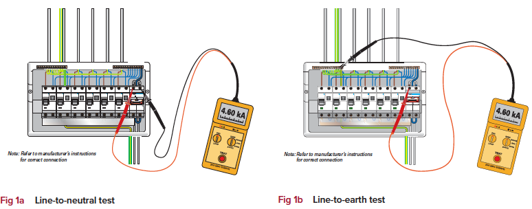 The maximum prospective fault current is the higher of the two fault currents (line-to-neutral or line-to-earth) and should be recorded on the certificate or report, as part of the details of the supply characteristics.
It should be appreciated that as the fault path for a TT system is through the general mass of earth, the measured value of earth fault current will be considerably lower than that obtained for an installation connected to a TN or TN-C-S arrangement.
Calculating the value of prospective fault current:
Where the test instrument does not have a prospective fault current range, the readings given by the previous tests will produce fault loop impedances (in ohms). To convert each of these readings into a prospective fault current, they should be divided into the voltage. For example, if the voltage measured at the time of the test is 230 V, and the measured value of fault loop impedance between line and neutral at the origin is 0.05 Ω:
Maximum prospective short-circuit current (line-to-neutral) = 230/0.05 = 4600 A (or 4.6 kA)
(This value would have been given directly if the instrument had a prospective fault current range).
The same procedure is now repeated to calculate the line-to-earth value, and the highest of these calculated values should be recorded as the maximum prospective fault current.
Three-phase supplies
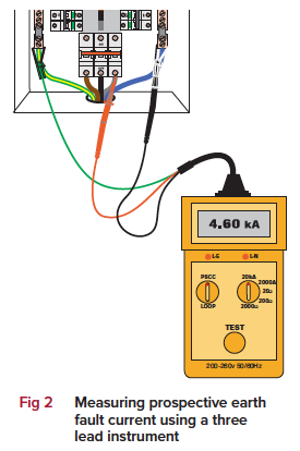
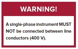
Where an installation is supplied by two or more phases, the maximum prospective fault current is likely to be between line conductors. Therefore, unless a test instrument designed to operate at 400 V is available to perform the test, it will be necessary to calculate the prospective fault current between lines. As a rule of thumb, the maximum prospective fault current for a three-phase supply, as shown in Fig 2, can be taken as twice the single-phase value. For example, if the maximum single-phase fault current measurement is 4.6 kA, then the maximum value of fault current between line conductors is calculated as:
4.6 kA x 2 = 9.2 kA.
The connection of a three lead instrument to measure single-phase earth fault current is shown in Fig 2, the test is repeated for each line.
To perform the short-circuit test, the green lead shown in Fig 2 is attached to the neutral (along with the black lead) and a short-circuit test performed for each line.

- For other guidance and publications please see the NICEIC website.
- For information about the NICEIC Approved Contractor or Domestic Installers schemes,visit www.niceic.com or call 0870 013 0382