
Carrying out an insulation resistance test gives an indication of the condition of the insulation of conductors and any equipment to which they are connected. Effective insulation is necessary to provide basic protection and to prevent short-circuits and earth faults.
An insulator should have high insulation resistance, typically many megohms. The insulation resistance of a conductor is inversely proportional to its length – that is, its insulation resistance decreases as the conductor’s length increases and vice versa. It follows that the insulation resistance of a complete electrical installation, or a section of it, will be less than that of a single circuit of that installation.
By reference to Table 61 of BS 7671, Regulation 612.3.2 indicates that the minimum acceptable value of insulation resistance for a distribution circuit with a distribution board or consumer unit and all its final circuits connected is 1megohm. Although values of this order particularly in a new installation, would warrant further investigation.
Prior to carrying out an insulation resistance test, any equipment likely to influence the test results obtained, or be damaged by the test voltage, such as surge protective devices, dimmers, electronic switches and high frequency luminaires, should be disconnected.
Where it is not reasonably practicable to disconnect such equipment, or where doubt exists as to whether all such equipment has been disconnected, the following options are available:
- Insulation resistance may be measured between live conductors and protective conductor(s) with all live (line and neutral) conductors connected together (Regulations 612.3.1 and 612.3.3 refer). Where this method is used, there is no potential difference between the line and neutral terminals of connected equipment that could adversely affect the internal components.
-
The test voltage applied may be reduced to 250 V d.c. but the minimum acceptable value of insulation resistance remains 1megohms (see Regulation 612.3.2).
RCDs may also affect insulation resistance test results. It may therefore be necessary to disconnect RCDs while the tests are performed and/or to test the wiring on the load side of RCDs separately, to ensure the wiring is included in the testing.
The procedure for performing insulation resistance testing as part of the initial verification of a single-phase low voltage (230 V) is as follows:
Temporarily disconnect or isolate equipment likely to be damaged by the test voltage or influence the test results. Place all switches in the ON position. Two-way and, where fitted, intermediate, switches will need to be operated during the test procedure to ensure that all live conductors are subjected to the testing.
Confirm that the circuit or circuits to be tested are de- energised and isolated. Then, using a high resistance ohmmeter set to 500 V d.c. and to the highest resistance range on the instrument, carry out the following test procedure and record the results obtained.
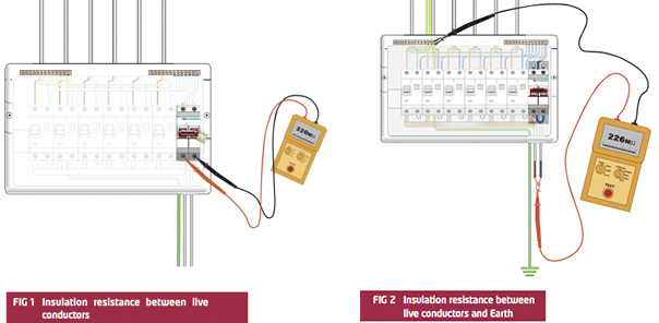
- Test between line and neutral on the load side of the main switch (in the OFF/isolation position, but with all the circuit protective devices in the ON position), as shown in Fig 1.
- Then test between live conductors and circuit protective conductor connected to the means of earthing (with the main switch and all the circuit protective devices in the ON position), as shown in Fig 2.
However, where the consumer unit has been connected to the meter, the test must be carried out on the load side of the main switch (in the OFF/isolation position, but with all the circuit protective devices in the ON position).
It is essential that, when performing an insulation resistance test between live and protective conductors, the protective conductors are connected to the earthing arrangement – that is, to the general mass of the Earth (Regulation 612.3.1 refers).
The connection to Earth is typically achieved by the protective conductor being connected to the main earthing terminal (MET) of the installation, to which the earthing and main protective bonding conductors are also connected, with the MET connected to the earthing arrangement (the distributor’s earthing facility (TN system) or the installation earth electrode (TT system), as applicable).
Having the protective conductors connected to Earth during the test has the advantage that the test might detect any contact between a live conductor and any ‘unearthed’ metalwork (such as a concealed part of the building fabric or an isolated section of pipework). If the unearthed metalwork has some relatively low resistance contact with Earth (even hundreds of thousands of ohms), the defect can be identified by the person using the insulation test instrument. Such a dangerous defect might be caused by the penetration of a nail, screw or similar making contact with a live conductor and the unearthed metalwork. If not corrected, the defect would create a risk of electric shock.
In many cases there will be a significant time interval between the initial placement of conductors (sometimes referred to as ‘first fixing’) and the final handover of the installation. It is possible for damage to have occurred during this time when, for example, cables were plastered over and flooring and ceilings were installed.
It is essential therefore that all the relevant inspection and tests are performed as part of the initial verification of the electrical installation. In many cases, this will require inspections and tests carried out earlier to be repeated. It may not be safe to rely on inspection and test results obtained at an early stage of the installation process.
Initial verification must be carried out by skilled person(s) competent in such work (Regulation 610.5). Where the inspection and testing has been carried out by an NICEIC Approved Contractor or an NICEIC or ELECSA Registered Domestic Installer, the results of the inspection and testing should be carefully reviewed by the registered Qualified Supervisor.
- For other guidance and publications please see the NICEIC website. Information about the NICEIC Approved Contractor or Domestic Installers schemes, visit www.niceic.com or call 0870 013 0382.