
The technical team at NICEIC take us step-by-step through the procedures involved when installing metal consumer units in installations forming part of a TT earthing system.

Prior to Amendment 3 of BS 7671, the typical consumer units installed in domestic installations employed a plastic all-insulated enclosure. However, from 1st January 20161, to meet the requirements of Regulation 421.1.201, all consumer units in domestic premises are required to either have an enclosure manufactured from a non-combustible material or be mounted in a cabinet constructed from a non-combustible material.
As a result, the installation of metal clad consumer units is likely to be the preferred option for achieving compliance with Regulation 421.1.201.
In view of this, contractors are reminded that where a metal clad (Class I) consumer unit is installed in an installation forming part of a TT system, an earth fault occurring between the incoming line conductor of the meter tails and the metallic enclosure, as shown in Fig 2, will not be detected by the RCD installed within the unit. Consequently, the metallic case of the unit and subsequently all other conductive parts connected to the main earthing terminal (MET) of the installation will rise to the supply potential (230 V to Earth), and in doing so expose persons to the risk of electric shock.
Furthermore, due to the high external earth fault loop impedance (Zs) of a typical TT system, which can often exceed 100 Ω, the earth fault current is unlikely to reach the level required to operate the service fuse, and even if it does the operating time is unlikely to be within the 1 s disconnection time required by BS 7671 (Regulation 411.3.2.4 refers).
For example, if the earth fault loop impedance is taken as 100 Ω then for a single phase supply the earth fault current that will flow under such fault conditions can be calculated as follows:
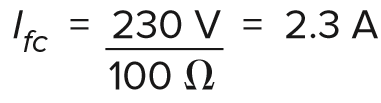
Clearly, this level of fault current is insufficient to operate an overcurrent protective device, therefore, unless a low value of Zs is assured so that the requirements of Regulation 411.5.3 for fault protection are satisfied, such a fault will remain uninterrupted. For this reason, it is preferred that earth fault protection for a TT installation is provided by an appropriately rated RCD (Regulation 411.5.2 refers).
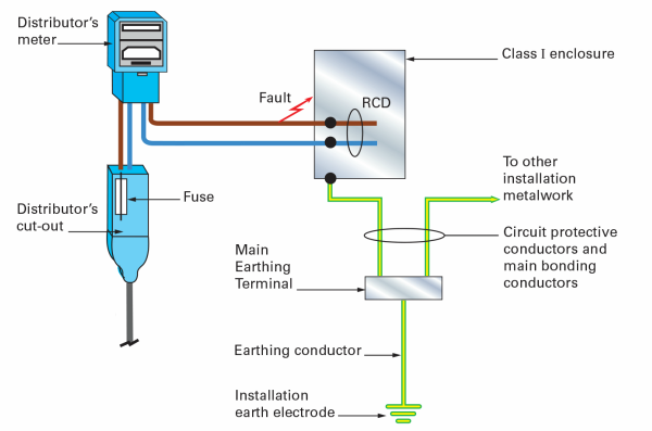
Fig 2. Effect of fault to earth between incoming tails and the metal case of a consumer unit.
Regulation 531.4.1 requires that for an installation which is part of a TT system and is protected by a single RCD then either:
1. the RCD is placed at the origin of the installation,
OR
2. the part of the installation between the origin and the device (RCD in the consumer unit) complies with the requirements for the protection by the use of class II equipment or equivalent insulation.
To achieve compliance with Regulation 314.1, regarding the division of the installation, consumer units installed in domestic installations commonly contain more than one RCD housed within the unit, known as dual RCD units. Installing an RCD upstream of the unit to provide additional protection for the meter tails would negate this provision.
Additionally, it is not possible to fit the double-pole RCD at a position that will eliminate all risk associated with protecting meter tails from earth fault. Therefore, such risks should be minimised by following the safe installation practice that has been applied by electrical contractors, for many years, when installing metallic units in installations forming part of a TT system. This includes:
• using thermoplastic or thermosetting insulated and sheathed cables for the meter tails, and
• positioning the consumer unit in close proximity to the energy meter to minimise the risk of damage to the meter tails, and
• fitting an insulated bush to protect the cables from abrasion, located where the meter tails enter the metallic consumer unit or protective cabinet (typical insulated bushes are shown in Fig 3).
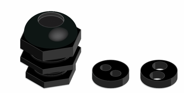
Fig 3 Typical insulated bushes for entries to Class I enclosures
It should be noted that in order to avoid eddy currents being induced in the metallic enclosure and causing overheating, all the meter tails should enter the consumer unit through the same entry point (that is through one knock-out hole). The requirement introduced in Regulation 421.1.201, is intended to ensure that if a source of ignition occurs within the enclosure of a consumer unit or switchgear assembly, such as arcing caused by a loose termination, for example, it is contained within the non-combustible enclosure and prevented from spreading externally. As such, the entry points of all cables (including the meter tails) into the metallic consumer unit should not, so far as reasonably practicable, unduly diminish the fire protection provided by the consumer unit enclosure.
It is generally accepted that this can be achieved by ensuring that the cable entries into the consumer unit maintain a degree of protection of at least IPXXD or IP4X for the top surface (Regulation 416.2.2 refers) and IPXXD or IP2X elsewhere (Regulation 416.2.1 refers).
Footnotes
1. Although Amendment 3 of BS 7671 came into effect on the 1st July 2015, to allow manufacturers of consumer units to make the necessary changes in their production processes, Regulation 421.1.201 came into effect on the 1st January 2016.
2. For additional protection, an RCD having a rating not exceeding 30 mA is required (Regulation 415.1.1 refers)
For information about the NICEIC Approved Contractor or Domestic Installers schemes, visit www.niceic.com or call 0870 013 0382.