
Approved Contractors and Domestic Installers will appreciate that conductors throughout an installation need to be identified, generally by colour, to indicate their function (and, for live conductors, their polarity), as required by Regulation Groups 514-03 to 514-06 and Appendix 7 of BS 7671.
However, a separate requirement of BS 7671, to which installers sometimes do not pay sufficient attention, is that:
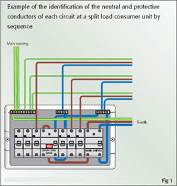
“As far as is reasonably practicable, wiring shall be so arranged or marked that it can be identified for inspection, testing, repair or alteration of the installation.” (Regulation 514-01-02 refers.) This requirement of Regulation 514-01-02 is particularly relevant at distribution boards and consumer units, although it also applies elsewhere throughout an installation. Where practicable, the wiring within a distribution board or consumer unit should be identified by arrangement.
This usually means connection of the neutral and circuit protective conductor of each circuit to the terminals that relate specifically to the associated outgoing fuse or circuit-breaker, either by sequence or terminal marking. Figure 1 shows an example of such connection by sequence.
In some types of distribution board or consumer unit (particularly some three-phase distribution boards), identification of the wiring by arrangement can be difficult, as the arrangement of the terminals on the neutral bar and/or earth bar does not correspond exactly with that of the phase terminals. This can lead to danger if, for example, an incorrect neutral conductor is disconnected as a result.
Where arrangement does not identify the wiring sufficiently well for the purposes of Regulation 514-01-02, the terminations of the conductors should be durably marked, such as with codings ‘1’, ‘2’, ‘3’ or ‘1L1’, ‘1L2’, ‘1L3’ etc, as appropriate. Figure 2 shows an example of marking applied to neutral conductors.
Marking of conductors using sleeves or ferrules, as shown in Figure 2, has the advantage that the conductors continue to be identified when disconnected from their terminals, such as for periodic testing. This aids, for example, safe reconnection of the conductors.