By: Eur Ing Graham Kenyon CEng MIET TechIOSH

The Energy Networks Association (ENA) recently published engineering recommendation (ER) P23/2:2018 Guidance on Earth Fault Loop Impedance at Customers’ Intake Supply Terminals, which supersedes ENA ER P23/1:1991 Consumers’ earth fault protection for compliance with the IEE Wiring Regulations for Electrical Installations.
In this article, Graham Kenyon provides an overview of the changes and considers how designers should treat earth fault loop impedance (Ze) in calculations for existing and, if required, new installations.
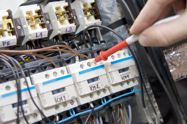
Industry has for many years been using the ‘maximum values’ of Ze published in ENA ER P23/1 1991. The values of Ze for supplies up to 100 A are shown in Table 1.
Table 1: Values of Ze for 230 V single-phase TN and TT supplies not exceeding 100 A according to ENA ER P23/1:1991
|
Supply arrangement |
Ze |
|
TN-C-S (Note 1) |
0.35 Ω (Note 2) |
|
TN-S |
0.8 Ω (Note 2) |
|
TT |
21 Ω (Note 3) |
Note 1: In ENA ER P23/1:1991, this value was quoted for both Protective Multiple Earthing (PME) and Protective Neutral Bonding (PNB) earthing arrangements. Higher values may apply where the consumer was supplied from small capacity pole-mounted transformers and/or long lengths of low voltage overhead line.
Note 2: The external earth fault-loop impedance for TT systems consists of the resistance of the neutral to earth plus the impedance of the transformer winding and line conductor, but does not include the resistance of the consumer's earth electrode.
The values in Table 1 have served as a reliable guide since their publication, although it has always been recognised that a small number of installations may fall outside these parameters, and represent an over-estimate (on the side of caution) for the majority of installations. They were never guaranteed for all installations, and for this reason, BS 7671 requires Ze be validated (by measurement or another valid method) during verification.
The changes in ENA ER P23/2:2018
ENA ER P23/2:2018, contains a set of values based on PD IEC/TR 60725:2012 Consideration of reference impedances and public supply network impedances for use in determining disturbance characteristics of electrical equipment having a rated current ≤ 75 A per phase. The quoted values for existing supplies up to 100 A are shown in Table 2.
Table 2: Values of Ze for existing 230 V single-phase supplies not exceeding 100 A according to EA ER P23/2:2018
|
Ze |
Comment |
|
0.34 Ω (0.25+j0.23) |
90% of premises will have an EFLI below this value. |
|
0.64 Ω (0.46+j0.45) |
98% of premises will have an EFLI below this value. |
|
Over 0.64 Ω
|
2% of premises will have an EFLI above 0.64 Ω. |
Note 1: These are typical maximum values and the measured value of Ze will change depending on the network configuration due to alterations, faults, maintenance and any embedded generation.
Note 2: Distribution network operators (DNOs) are under no obligation to design or maintain networks to provide a particular maximum value of Ze. Many DNOs do, however, have their own internal quality and design standards, which often align with the Ze values in Table 1.
Note 3: The values for new networks are available from the DNO.
Note 4: The typical maximum Ze quoted in P23/1 was 0.8 W for a TN-S service with a capacity of up to 100 A.
These recommendations will be reflected in the suite of IET guidance publications that accompany the 18th Edition of the IET Wiring Regulations, including:
The On-Site Guide (IET Wiring Regulations 18th Edition)
Student's Guide to the IET Wiring Regulations, 2nd Edition 2018
Guidance Note 5: Protection against electric shock, 8th Edition 2018
Guidance Note 6: Protection against overcurrent, 8th Edition 2018
Electrical Installation Design Guide, 4th Edition 2018
Further information can be found in the relevant guidance publications.
To read the full article, please visit Wiring Matters.
Graham is Managing Director and Principal Consultant, G Kenyon Technology Ltd
Chair, IET Wiring Regulations Policy Committee Deputy Chair, JPEL/64 (IET Wiring Regulations) Sub-Committee D (Special locations and external influences)