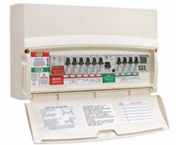
The IET’s technical helpline has taken a number of calls of late asking how three- and four-pole RCDs operate and how they are to be physically tested. This article looks to answer these and related questions.

The requirements of BS 7671:2008 for testing of residual current devices have been covered a number times in previous issues of Wiring Matters (see the Further Information section at the end of this article on how to obtain back issues), therefore, this information will not be repeated.
Residual current devices BS 7671:2008 carries the following definitions:
Residual current device (RCD)
A mechanical switching device or association of devices intended to cause the opening of the contacts when the residual current attains a given value under specifi ed conditions.
Residual current
Algebraic sum of the currents in the live conductors of a circuit at a point in the electrical installation.
An RCD is a protective device used to automatically disconnect the electrical supply to a part of the electrical installation when an imbalance is detected between live conductors. Note that the term “live conductors” means a conductor or conductive part intended to be energised in normal use, including a neutral conductor but, by convention, not a PEN conductor.
RCD is the generic term for a device that operates when the residual current in the circuit reaches a predetermined value. The RCD is, therefore, the main component in an RCCB or one of the functions of an RCBO:
RCCB - Residual current circuit-breaker - an example is a main switch in a consumer unit protecting the circuits of a number of circuit-breakers in a split-load board.
RCBO - Residual current operated circuit-breaker with integral overcurrent protection is an RCD and (miniature) circuit-breaker combined
If a line-to-earth fault develops or current flows in the protective conductor, some of the line conductor current will not return to the source of supply through the neutral conductor. When this residual current reaches a preset limit (the residual operating current - IΔn), the RCD detects
this imbalance, operates and disconnects the circuit from the supply.
Single-phase devices
In the case of a single-phase circuit, the RCD will be two-pole and the device will monitor the
difference in currents between the line and neutral conductors. The monitoring or sensing component is usually a coil or torroid. In a healthy circuit, where there is no earth fault current or
protective conductor current, the sum of the currents in the line and neutral conductors is zero.
Note that faults between line and neutral conductors (shortcircuit) are not detected by RCDs, these faults are detected by fuses, circuit-breakers or the overcurrent protection stage of an RCBO.
Test Circuit
A test circuit is always incorporated in the RCD. Operation of the test button connects a
resistive load between the line conductor on the load side of the RCD and the supply neutral. The test circuit is designed to pass a current, in excess of the tripping current of the RCD, to simulate an out-ofbalance condition. Operation of the test button checks the electromechanical integrity of the RCD only.
Regulation 514.12.2 of BS 7671:2008 requires that on all installations where RCDs are present, a notice shall be fixed in a prominent position at or near the origin of the installation,
instructing the user to check the function of the RCD by pressing the test button every three months and to observe that the RCD trips instantly.
It is important to note that the RCD should still be verified by regular periodic inspection, the
testing requirements for which, are given in Regulation 621.2.
To view the full article and tables from the IET's Wiring Matters Spring 2010, click on the attachment below...
