Questions commonly asked on the NICEIC Technical Helpline...
Maximum Length of Meter Tails
Question: What is the maximum length of meter tails?
Answer: The maximum permitted length of meter tails is determined by the Electricity Distributor. Different distributors have different requirements. Normally, the Electricity Distributor will decide on the position of the cutout and meter and will state the maximum length permitted for meter tails, such as 2 or 3 metres. In the event that the Distributor’s requirements cannot be met, the electrical installation designer will be obliged to design a suitable distribution circuit, (sub-main), to connect the distribution board to the origin of the installation. This will normally be accomplished by providing, close to the origin, a device such as a switch-fuse to permit the requirements for isolation, overcurrent protection and discrimination to be met for the distribution circuit.
Explanation: ‘Meter tails’ is the term generally used to describe the conductors connecting between the electricity supply meter at the origin of an installation and an item of switchgear or controlgear, or a distribution board such as a consumer unit. As such, meter tails are simply a particular form of distribution circuit. Like all conductors, meter tails are required to be protected against overcurrent and to be provided with a means of isolation.
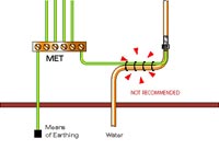
Protection: Devices for protection against overload and fault current for meter tails at the origin of an installation may be omitted provided the Electricity Distributor agrees that the protection at the supply cutout is suitable and can be so used (Regulations 473-01-04 and 473-02-04 refer). A condition of the Electricity Distributor’s agreement may be a restriction on the length of the meter tails. It is essential that this and any other pre-conditions are complied with.
Discrimination: Where necessary to prevent danger, any intended discrimination between the protective device for the distribution circuit and the Electricity Distributor’s protective device must be achieved.
Isolation: The Electricity Distributor’s equipment may be used to isolate meter tails and other equipment immediately downstream, subject to the Distributor’s express agreement (Regulation 476-01-01 refers).
Concealed cables: Where meter tails are concealed under plaster or other building fabric at a depth of less than 50 mm from any surface of the wall or partition, the requirements of Regulation 522-06-06 must be met (see Amendment 2 to BS 7671). There are a number of options available to meet these requirements, including running the meter tails in designated ‘safe’ zones or providing mechanical protection sufficient to prevent penetration by nails, screws and the like.
Metal Cable Tray or Basket
Question: Should metal cable tray or basket be earthed or bonded?
Answer: Normally not, unless there are exceptional circumstances.
Such exceptional circumstances include:
i. If the installation designer has selected the cable tray for use as a protective conductor which is permitted under indent (vi) of Regulation 543-02-02 ‘an electrically continuous support system for conductors.’ The cable tray would be required to meet the requirements for a protective conductor and would need to be connected with Earth.
ii. If the cable tray meets the definition of an extraneous-conductive-part then main equipotential bonding will be required.
Explanation: In practice, unless there are exceptional circumstances such as those indicated above, the conductive parts of a cable support system such as metal cable tray or basket will neither be exposed-conductive-parts nor extraneous-conductive-parts. Consequentially, cable tray or basket need not be earthed or equipotentially bonded.
Turning, first, to the question of earthing.
Should the cable tray or basket be earthed?
Electrical equipment such as cables mounted on a metallic support system will normally be of either equivilent to Class I construction (for example copper sheathed, mineral insulated cables without an overall pvc covering) or Class II equivalent construction (for example pvc insulated and sheathed cable).
Exposed-conductive-parts of cables (such as the copper sheath of a mineral insulated (MI) cable) are required to be connected to the Main Earthing Terminal of the installation by a circuit protective conductor designed to conduct earth fault current. The cable tray or basket to which the MI cable is attached, or may be in contact with, is not itself an exposed-conductive-part and hence does not need to be earthed.
A cable complying with the appropriate standard having a non-metallic sheath or a non-metallic enclosure is deemed to provide satisfactory protection against both direct and indirect contact, as does an item of Class II equipment (Regulation 471-09-03 refers). Class II equipment is constructed such that any insulation fault in the cable cannot result in fault current flowing into any conductive parts with which the equipment may be in contact. Hence the metal cable tray or basket need not be earthed.
Generally, the conductive parts of a metal cable tray or basket system need not be intentionally earthed. Some conductive parts of a metal cable support system may be earthed, however, by virtue of fortuitous contact with exposed-conductive-parts.
Should the cable tray or basket be equipotentially bonded?
Unless a metal cable support system will introduce a potential that does not already exist in the location in which the system is installed, it will not meet the definition of an extraneous- conductive-part. In normal circumstances, therefore, there is no need to arrange for the conductive parts of the support system to be connected to either a main bonding conductor or to any supplementary bonding conductor.
Note, however, that should the cable tray be installed in such a manner that it is likely to introduce a potential from outside the location, thereby meeting the definition of an extraneous- conductive-part, then main equipotential bonding will be required (Regulation 413-02-02 refers). For example, consider a run of cable tray carrying services into a particular building. The cable tray may be in contact with Earth potential outside a building and upon entering into the building would be likely to introduce earth potential into that building. In such a case main equipotential bonding would be required.
Support of Bonding Cables
Question: Can cables such as bonding cables be supported by a gas or water pipe?
Answer: No, unless there is no reasonably practicable alternative in difficult or unusual circumstances. In all but the most unusual circumstances, bonding cables should be separately supported (Regulation 133-01-01 refers to good workmanship when erecting an installation).
Explanation: Main equipotential bonding conductors and supplementary equipotential bonding conductors should not be supported by the service to which they are connected (for example tie-wrapped).
As with all conductors, main bonding conductors should be adequately supported without using non-electrical services such as pipework as a means of support. Where a wiring system is to be installed in proximity to a non-electrical service it shall be so arranged that any forseeable operation carried out on either service will not cause damage to the other (Regulation 528-02-04).
Attention must also be paid to the ability of main bonding conductors to withstand external influences such as mechanical damage etc (Section 522), and any anticipated factors likely to result in deterioration (Regulation 543-03-01 refers).
Cables in Cavity Walls
Question: Can cables be run in external walls with cavities?
Answer: Cables such as pvc/pvc insulated and sheathed cables should not be run in cavity walls. Mineral insulated copper sheathed cables may be judged by the installation designer to be suitable for such a location.
Explanation: Electrical installation designers often have to consider whether it is permissible to install thermoplastic (pvc) insulated and sheathed cables in external cavity walls. The NICEIC considers that installing such cables in this way is generally an undesirable practice, as it is unlikely that all of the applicable requirements of BS 7671, the Building Regulations and the NHBC requirements listed below will be fully met.
Damage to cables during installation. Obstructions in a cavity wall, such as metal wall ties or mortar projections, create a risk of unseen damage occurring to the cable sheath and conductor insulation during installation. (Regulation 522-08-01 refers).
Strain on cables lacking support. Long unsupported vertical drops may place undue strain on the conductors, leading to damage (Regulation 522-08-04 refers).
Materials liable to cause mutual or individual deterioration. Expanded polystyrene sheets, granules or foam may be used in buildings for thermal insulation purposes. If this material comes into contact with thermoplastic (pvc) cable sheathing, plasticiser can migrate from the thermoplastic to the polystyrene. The thermoplastic sheathing then becomes less flexible and the polystyrene becomes soft and tacky. Such contact should be avoided. (Regulation 522-05-03 refers).
Cables in thermal insulation. Thermal insulation is often installed in cavity walls during or after construction. Cables in the cavity may not then be able to carry the load current without overheating due to their current-carrying capacity being reduced. For example, where a cable is surrounded by thermally insulating material over a length of 500 mm or more, the cable current- carrying capacity is to be taken as half the ‘clipped direct’
Method 1 rating unless more precise information is available (Regulation 523-04-01). Cables should be installed where they will not come into contact with thermal insulation (present or reasonably to be expected in the future) unless the current-carrying capacity is adequately maintained by, for example, increasing the cross-sectional area of the conductors at the design stage.
Presence of flora and fauna. Designers and installers may not necessarily detect or predict the presence of flora or fauna in a cavity wall. The wiring system should be selected to withstand all the external influences expected, or damage to cables may occur from, for example, mould or rodents (Regulations 522-09-01 and 522-10-01 refer).
Building Regulations. Building Regulations 2000, Approved Document C, 1992 Edition, Section 4: Walls, paragraph 4.12 b Cavity external walls, states:
‘A cavity external wall may be built with the cavity at least 50 mm wide. The cavity is to be bridged only by wall ties or by damp-proof trays provided to prevent moisture being carried to the inner leaf.’
A cavity is intended to provide a gap to prevent water penetration. Cables could bridge this protection if they touch both the inner and outer leaves of a cavity wall. Furthermore, the cables could provide a route for water to drain directly into accessories, with potentially dangerous results.
NHBC Requirements. It is noteworthy that the National House-Building Council states, in Section 8.1 - S2 of NHBC Standards, that no cables other than electricity meter tails are to be located in the cavity of an external wall. Where meter tails do have to pass through the cavity, however, this does not preclude the requirements of
BS 7671 referred to in this article having to be met.
Plate Switch in a Lavatory Containing a Sink
Question: Can a plate switch be installed in a lavatory containing a sink?
Answer: Yes.
Explanation: A question sometimes arises of whether wall-mounted lighting switches and other such accessories are permitted in lavatories. A lavatory is not a location of increased shock risk, as defined. The general requirements of BS 7671 are applicable to such locations and Regulation 512-06-01 calls for every item of equipment to be of a design appropriate to the situation in which it is to be used, or its mode of installation must take account of the conditions likely to be encountered. Like other equipment that may be considered for installation in a lavatory, normal wall-mounted lighting switches and similar accessories may not have a degree of ingress protection appropriate for installation in the particular location and would therefore not satisfy the requirements of BS 7671.
The requirements of BS 7671 may be met by means such as:
i. Installing the wall-mounted light switch in a convenient position outside of the lavatory.
ii. If a wall-mounted plate switch must be installed within the room and is likely to be splashed or operated with wet hands, the switch should have an IP rating suitable for its location.
iii. Employing a pull-cord switch complying with BS 3676 with an IP rating suitable for its location. The body of the switch should be installed outside of the area where a plate switch is likely to get splashed or operated with wet hands but the pull cord itself is permitted to enter such an area but should be of insulated material.
Socket-outlet Installed on to a Wooden Panel
Question: Can a socket-outlet be installed on to (surface-mounted) or in a wooden panel (flush-mounted)?
Answer: Yes, but the connections must be suitably enclosed.
Explanation: The connections from the cable(s) to the socket-outlet must be made within a suitable enclosure (Regulation 526-03-02 refers).
For example, if a socket-outlet is to be surface-mounted on a wooden panel, it must be mounted on a suitable non-combustible back box. Alternatively, if the socket-outlet is to be flush-mounted, the connections must, once again, be enclosed in non-combustible material. The wood of the panel may not meet the glow-wire test requirements, non-combustibility or ignitability requirements embodied in Regulation 526-03-02.