
When electricians are carrying out inspection and testing, commonly they will make an engineering judgement about whether the values of resistance that they measure are reasonable.

One such judgement involves determining whether the end-to-end resistance of a circuit protective conductor (cpc) in a ring final circuit is reasonable when compared with the end-to-end resistances of the line and neutral conductors.
Typically electricians have reckoned that the resistance of the cpc when compared with that of the line and neutral conductors is always in the order of 1.67 times greater. However, the ratio of the end-to- end resistances of the circuit protective conductors (cpc) and live conductors for flat twin and earth cable is not always 1.67.

When measuring the end-to-end resistances of ring final circuit conductors wired in flat twin and earth cable, it is important to recognise that if the conductors are not of the same length or have a cross-sectional area (csa) other than 2.5 mm2 for the line and neutral conductors and 1.5 mm2 cpc the resistance ratio will not be 1.67.
For every ring final circuit a test is required to verify the continuity of each conductor, including the cpc (Regulation 612.2.2 refers).
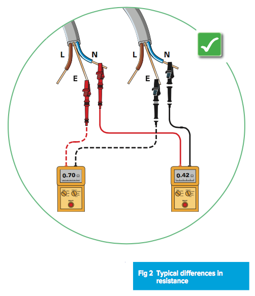
Typical ring final circuits
Domestic ring final circuits are, more often than not, wired using flat win and earth cable having 2.5 mm2
2 line and neutral conductors and 1.5 mm2 cpc. Where this is the case, the expected end-to-end resistance values measured for each loop of conductor should result in the cpc having a resistance approximately 1.67 times that of the line or neutral loop. This is due to the ratio of their csas (that is, 2.5/1.5 = 1.67).
Non-typical ring final circuits
However, a ring final circuit may need to be wired using flat twin and earth cable with larger conductor sizes. This may be due, for example, to designing for voltage drop considerations or because the cable will be covered with thermal insulation. Where the live conductor size is larger than 2.5 mm2, the ratio of the resistance of the cpc to that of the line or neutral conductor will not be 1.67, and the thoughtful electrician may make an error of judgement when determining whether the values are consistent. For example, where the flat twin and earth cable has 4.0 mm2 line and neutral conductors and 1.5 mm2 cpc, the ratio should be approximately 2.67 (given by 4.0/1.5 = 2.67). The same approach would apply also for other sizes of flat twin and reduced cpc cable.
Indeed, where, exceptionally, a ring final circuit is wired using some other type of cable (such as armoured cable or mineral insulated cable), this may result in the cpc having a copper equivalent csa greater than the line and neutral conductors. Under such conditions the expected end-to-end resistance values measured for each loop of the line and neutral conductors would have a value higher than the cpc. It is also the case that the 1.67 rule of thumb will fail where the circuit is installed in steel conduit or trunking and where the protective conductor is the metal of the conduit or trunking.
Be careful, therefore, when rushing to judgement to ensure that you are not rejecting perfectly healthy circuits.
Table for common combinations of flat twin and cpc cable used for ring final circuits.
| Line conductor (mm2) | Cpc (mm2) | Expected ratio |
| 2.5 | 1.5 | 1.67 |
| 4.0 | 1.5 | 2.67 |
| 6.0 | 2.5 | 2.4 |
For other guidance and publications please see the ELECSA website.
For information about the ELECSA schemes, visit www.elecsa.co.uk or call 0333 321 8220