This article considers some common questions asked related to ring final circuits.

NICEIC is sometimes asked whether a ring final circuit has to be supplied directly from a protective device in the distribution board or consumer unit, or whether it is permitted to supply the two ends of the ring via a dedicated radial circuit cable, as shown in Fig. 1, thereby forming a hybrid ring/radial circuit.
This question can arise where, for example, the contractor wishes to make use of a redundant radial circuit cable previously installed for another purpose (such as a cooker circuit) to supply a ring final circuit, or where a Periodic Inspection of an existing installation reveals such an arrangement.
The same question may also arise where the contractor wishes to control a ring final circuit by means of a switch for functional purposes, or possibly by means of a contactor, controlled by an emergency stop push button (such as in a teaching situation), the supply being brought to the switch or contactor via a dedicated radial circuit cable.
The answer is that it is permissible to form a hybrid ring/radial circuit, even though BS 7671 defines a ring final circuit as ‘A final circuit arranged in the form of a ring and connected to a single point of supply’. For such a hybrid circuit, the ‘single point of supply’ is the point at which the two ends of the ring part of the circuit are connected to the radial part (that is, at the junction box, switch or contactor as labelled in Fig 1). A hybrid ring/radial final circuit must be arranged to meet all the relevant requirements of BS 7671, as amended, the main ones of which are summarised as follows.
Protection against electric shock
As for any other final circuit, the requirements of Chapter 41 for electric shock protection have to be met, including those of Section 411 for earth fault loop impedance (Zs) and, where applicable, RCD additional protection of the socket-outlets (In ≤ 30 mA) in accordance with Regulation 411.3.3. Also, if any part of the circuit cable is concealed in a wall or partition, it must be provided with additional protection by an RCD (In ≤ 30 mA) as required by Regulations 522.6.202 and 522.6.203.
Cable sizing with regard to normal load and overload
The current-carrying capacity (Iz) of the cable in the radial part of the circuit must be not less than 30 A or 32 A, to match the circuit overcurrent protective device rating (In) of 30 A or 32 A. Where the protective device is a semi-enclosed (rewireable) fuse, Iz must not be less than In divided by 0.725. Regulation 433.1.202 refers.
The ring part of the circuit must meet the same overload protection requirements as for any other ring final circuit, which is usually achieved through compliance with Regulation 433.1.204.
Despite the non-conventional form of a hybrid ring/ radial circuit, the total load current (Ib) to be supplied by the circuit, making due allowance for any diversity, must still be no greater than the 30 A or 32 A rating of the circuit protective device. Thus, for example, the floor area served by the circuit should be no greater than would be the case if an ordinary ring final circuit having the same protective device rating was installed instead of the hybrid circuit.
Accessibility of connections
As is required for all electrical connections, the connections between the radial and ring parts of the circuit (in the junction box, switch or contactor in Fig 1) must be arranged to be accessible throughout the life of the installation for inspection, testing and maintenance (Regulation 132.12 refers).
Voltage drop
Account must be taken of the voltage drops in both the radial and ring parts of the circuit. These voltage drops added together make up the total voltage drop in the circuit. This may mean, for example, that the maximum allowable length of the ring part of the circuit will be less than that for a ring final circuit connected directly to the distribution board.
Protective conductor in the ring part of the circuit
Except where the circuit protective conductor in the ring part of the circuit is formed by a metal covering (such as a metallic cable sheath) or enclosure (such as metal conduit) containing all the conductors of the ring, the protective conductor must be run in the form of a ring, as required by Regulation 543.2.9. Both ends of the protective conductor ring must be connected to the earthing terminal at the origin of the ring (that is, the junction box, switch or contactor in Fig 1).
Earthing for equipment having high protective conductor currents
If the circuit is intended to supply one or more items of equipment where it is known or reasonably to be expected that the total protective conductor current is likely to exceed 10 mA, the circuit will require a high integrity protective conductor connection in accordance with Regulation Group 543.7.
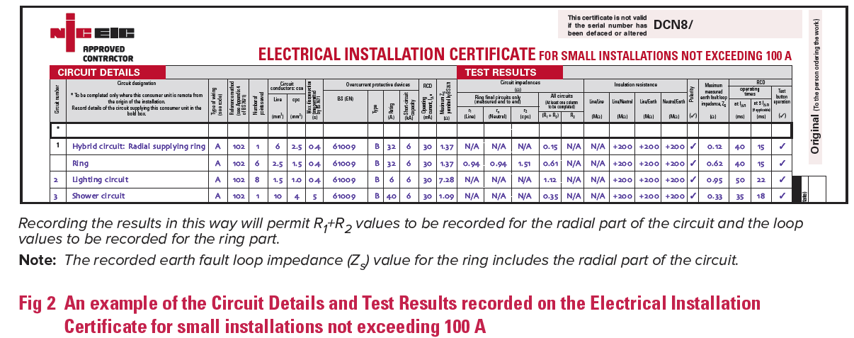
Electrical Testing
For verification of the hybrid ring/radial circuit, the circuit details and test results for each part of the overall circuit, the radial and the ring parts, should be recorded separately on the appropriate schedule contained in the NICEIC Electrical Installation Certificate for Small Installations not exceeding 100 A, as shown in Fig 2, or where appropriate on an EIC.
Use of a standard circuit might be easier
It will be appreciated from this article that the use of a hybrid ring/radial circuit arrangement can involve significant design effort. As an alternative, for household and similar installations, installers should consider the use of the standard ring or radial socket-outlet circuit arrangements shown in Appendix 15 of BS 7671, for which tables of maximum cable length are given in the NICEIC Site Guide for Electrical Installations.
• For other guidance and publications please see the NICEIC website.
• For information about the NICEIC Approved Contractor or Domestic Installers schemes, visit www.niceic.com or call 0870 013 038