
Understanding its impact on electrical safety and compliance.

Accurate loop impedance testing sits at the heart of electrical safety, providing the assurance that protective devices will operate correctly when a fault occurs. Every calculation, every recorded value, and every certification decision depends on the assumption that the measurement taken reflects the true condition of the installation. When that assumption is wrong, even by a small margin, the consequences can be far more serious than many realise.
One of the most common and least understood causes of inaccurate loop impedance results is a phenomenon known as RCD uplift. It occurs when the presence of a Residual Current Device (RCD) or RCBO artificially inflates the loop impedance reading during a no-trip test, creating a discrepancy between what is measured and the true impedance of the circuit itself. The result is uncertainty at precisely the point where certainty matters most.
This article provides a clear, technical explanation of what RCD uplift is, why it occurs and why it should not be ignored. It also explores the real-world implications for electrical safety, compliance with BS 7671 and day-to-day testing efficiency, before outlining how modern testing technology can remove this uncertainty altogether.
The Technical Foundation of RCD Uplift
Defining RCD Uplift and Its Origin
What Is RCD Uplift?
RCD uplift is the additional impedance contribution introduced by an RCD or RCBO during a no-trip loop impedance test. This added value is not part of the actual earth fault loop impedance of the installation, but an artefact of the test method interacting with the protective device.
No-trip testing is essential when measuring loop impedance on circuits protected by RCDs, as it allows the test to be performed without disconnecting supply or causing unwanted tripping. However, while this approach protects continuity of service, it introduces a known limitation: the measured value can include impedance effects from the RCD itself rather than from the circuit conductors and earth path.
Understanding this distinction is critical. RCD uplift does not indicate a wiring fault, poor connections or degraded conductors. It is a measurement distortion created by the test environment.
The Cause: Interaction Between Test Current and RCD Components
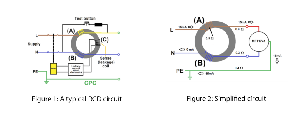
At the centre of every RCD is a magnetic core, designed to detect imbalance between live and neutral conductors. During normal operation, this core remains stable and highly sensitive to fault conditions.
During a no-trip loop test, however, the tester injects a low-level test current intended to avoid triggering the RCD. Under these conditions, the interaction between the test signal and the RCD’s internal magnetic and electronic components can cause partial magnetic saturation of the core. This saturation introduces an additional impedance that the tester cannot distinguish from the true loop impedance of the circuit.
As a result, the instrument reports a higher Zs value than actually exists. The uplift varies depending on RCD design, sensitivity and the characteristics of the test signal, which is why results can appear inconsistent or difficult to explain in the field.
The Critical Impact of RCD Uplift on Safety and Compliance
Compromised Safety Through Incorrect Fault Current Calculation
Loop impedance measurements are not taken in isolation. They are used to calculate prospective fault current (PFC) and to verify that protective devices will disconnect within the required time under fault conditions.
When RCD uplift inflates the measured Zs value, the calculated fault current appears lower than it actually is. This can lead an electrician to believe that disconnection times are marginal or acceptable when, in reality, the behaviour of the protective device under fault conditions has not been accurately verified.
In a real fault scenario, this uncertainty matters. If a device does not operate within the required time, the risk of electric shock or thermal damage increases significantly. What appears to be a compliant installation on paper may not deliver the level of protection assumed.
Non-Compliance with IET Wiring Regulations
BS 7671 sets clear maximum Zs values to ensure automatic disconnection of supply within defined time limits. When RCD uplift skews loop impedance results, a perfectly sound installation can appear to exceed these limits.
This places electricians in a difficult professional position. They may be forced to question their own workmanship, investigate non-existent faults or record advisory comments that do not reflect the true condition of the installation. Over time, this erodes confidence in test data and undermines the value of certification itself.
Operational Inefficiency and Wasted Time
Beyond safety and compliance, RCD uplift has a very real impact on productivity. Inflated readings often trigger unnecessary investigation, repeated testing or time-consuming checks of connections and bonding that are already sound.
In busy environments where downtime matters, this lost time adds up quickly. What should be a straightforward verification becomes an exercise in second-guessing results, often without a definitive explanation.
Mitigation and Modern Technological Solutions
Recognising the Limitations of Traditional Testing
No-trip loop testing remains essential, but it should never be treated as infallible. Understanding its limitations, particularly in the presence of RCDs and RCBOs, is part of professional competence.
Relying on results that may include RCD uplift without recognising the risk introduces uncertainty into safety-critical decisions. Awareness alone, however, does not solve the problem. A reliable measurement method is required.
The Definitive Solution: Advanced Loop Testing Technology
Modern multifunction testers now incorporate advanced, patented measurement techniques designed specifically to address RCD uplift. These systems analyse the test response in greater detail, allowing the instrument to distinguish between the true circuit impedance and the additional impedance introduced by the RCD.
Technologies such as True Loop® actively identify and remove the uplift component from the final displayed value, delivering a result that represents the actual earth fault loop impedance of the installation, even during no-trip testing.
Building Confidence in Results
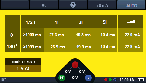
Advanced testers also provide visual confirmation that the measurement is stable and trustworthy. Features such as a confidence or stability indicator allow the user to see, in real time, that external influences have been managed and that the displayed value can be relied upon.
This removes guesswork from the process and restores confidence in both the measurement and the decisions based on it.
Conclusion: Upholding a Higher Standard of Electrical Safety
RCD uplift is a measurable and predictable phenomenon that affects no-trip loop impedance testing. When left unaddressed, it inflates Zs readings, distorts fault current calculations and introduces uncertainty into safety-critical decisions.
These inaccuracies can lead to apparent non-compliance with BS 7671, unnecessary remedial work and wasted time, while also masking the true performance of protective devices under fault conditions.
Understanding RCD uplift is a professional responsibility, but awareness alone is not enough. Reliable, modern test instruments now provide a definitive solution, delivering accurate loop impedance measurements without compromising safety or continuity of supply.
The presence of RCD uplift is not a failing of the RCD itself, but a limitation of conventional test methods. By adopting advanced measurement technology, electrical professionals can remove this variable entirely and ensure that their work is not only compliant, but fundamentally safe.
Ensure your loop impedance testing delivers absolute certainty.
Explore the capabilities of the MFT-X1 With True Loop® technology