










Published: 29 May 2022
Category: Technical articles
Skip to content
-
-
Premium 8
-
Manufacturer 39
-
 Adaptaflex

-
 APC
APC
-
 BG Electrical
-
 Brady
Brady
-
 British Cables Company
-
 CPN Cudis
-
 Crabtree
-
 Dehn
Dehn
-
 Di-Log
-
 Doepke
-
 E-Klips
-
 Eaton
Eaton
-
 Electrium
-
 Emergi-Lite
-
 Fibox
Fibox
-
 flex7
flex7
-
 Furse
Furse
-
 Interact
-
 Kewtech
-
 KOPEX
KOPEX
-
 LEDVANCE
-
 Linian
-
 Luceco
-
 Marshall Tufflex
-
 Martindale Electric
-
 Masterplug
-
 Megger
-
 Nexans
-
 Philips
-
 Quickwire
-
 Rointe
-
 Shelly
-
 Siemens
-
 Signify
-
 Sync Energy
-
 TWISTTAIL
-
 TY-MET
-
 TY-RAP
-
 Wylex
Wylex
-
-
Distributor 8
- All partners
-
Shopping Cart

Resistors connected in parallel
The aim of this article is to consider how voltage, current and power are affected by parallel connected loads. This will be complemented using a few examples. (Please note, all information shown is correct as of date of issue.)
NICEIC
Resistors connected in parallel
Published: 29 May 2022 · Category: Technical articles
The aim of this article is to consider how voltage, current and power are affected by parallel connected loads. This will be complemented using a few examples. (Please note, all information shown is correct as of date of issue.)
From this document
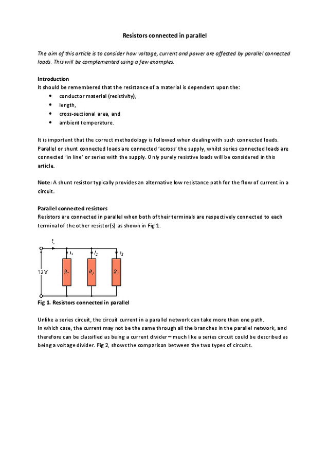
Resistors connected in parallel The aim of this article is to consider how voltage, current and power are affected by parallel connected loads. This will be complemented using a few examples. Introduction It should be remembered that the resistance of a material is dependent upon the: • conductor material (resistivity), • length, • cross-sectional area, and • ambient temperature. It is important that the correct methodology is followed when dealing with such connected loads. Parallel or shunt connected loads are connected ‘across’ the supply, whilst series connected loads are connected ‘in line’ or series with the supply. Only purely resistive loads will be considered in this article. Note: A shunt resistor typically provides an alternative low resistance path for the flow of current in a circuit. Parallel connected resistors Resistors are connected in parallel when both of their terminals are respectively connected to each terminal of the other resistor(s) as shown in Fig 1. Fig 1. Resistors connected in parallel Unlike a series circuit, the circuit current in a parallel network can take more than one path. In which case, the current may not be the same through all the branches in the parallel network, and therefore can be classified as being a current divider – much like a series circuit could be described as being a voltage divider. Fig 2, shows the comparison between the two types of circuits. a) Series. Voltage divides across R1 and R2 b) Parallel. Current divides...
Open the PDF