Published:
5 August 2013
Category: Product Catalogues & Brochures
Shopping Cart
You currently have no products eligible for checkout.
0 points
Purchase products from our manufacturer partners at participating wholesalers to earn points, redeemable in our Voltimum+ Rewards Shop. Join our Voltimum+ loyalty programme today!
Distributor Selection
Select the distributor you would like to use for your shopping cart.
Distributor

Schneider Electric - C-Bus technical selection guide
A 60 page, full colour catalogue that looks at C-Bus technical selection. This catalogue provides information on C-Bus technical selection
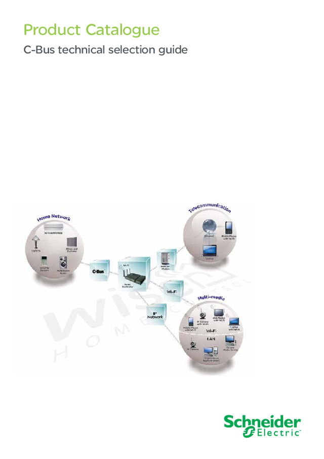
Product Catalogue C-Bus technical selection guide
3 Contents Introduction 4 Key input units 5 Input units 15 System units 32 Output units 39 Software packages 57
4 Introduction Clipsal, a brand of Schneider Electric, is dedicated to supplying end-to-end building management and integrated control with the products, solutions and programs to help meet customers expectations. Utilising the Schneider Electric product basket, complete end-to-end solutions are possible with products catering for any type or size of installation. With solutions ranging from power and lighting control, dimming, energy management, for home automation and commercial applications. The Clipsal C-Bus ® system is a microprocessor based wiring system to control lighting and other electrical services. Whether on/off control of a lighting circuit or analogue type control such as dimming electronic fluorescent ballasts, C-Bus can be used to control and automate virtually any type of electrical load. To ensure fast and reliable operation, each device has its own inbuilt microprocessor, which can be individually programmed via ‘point and click’ PC based software, or via ‘learn mode’ which doesn’t require a PC. C-Bus information is held within individual units rather than one central point. This ensures optimum communication speed and reliability. Whilst a computer is not necessary for normal C-Bus operation, PC based control and management software is available and provides additional flexibility to clients requiring this type of control.
Key input units
6 Saturn input switches Key Input units E5084NLGF The Saturn series key Input units are learn enabled surface switches designed to control lighting and other electrical services connected to a C-Bus network. Suitable for exclusive interiors. The round silver finish push buttons feature a dual coloured light indicator, providing a visual indication of the switch state. Key Input units are fully programmable and may be configured as toggle, dimmer, timer or scene control type functions. With C-Bus switches it is possible to realise multi-way, multi-function switching or dimming control. Product features ■ ■ Features bi-colour light indicator with night light ■ ■ Programmable using learn mode or via the C-Bus Toolkit Software ■ ■ Programmed variables are stored in non-volatile memory and are retained in case of loss of C-Bus power ■ ■ Features, 60.3mm mounting centres ■ ■ Available in glass finish with white, black, cream or mid-brown background Technical information C-Bus Supply Voltage 15-36VDC @ 22mA Maximum Number of Units on a Single C-Bus Network 50 Status Indicator Programmable, Dual, Orange and Blue Timer Range 1 sec to 18 hrs Timer Resolution 1 sec Dimmer Control 255 possible levels Mounting Centres 84mm Operating Temperature Range 0˚C to 45˚C Operating Humidity Range 0 - 95% RH, non-condensing Dimensions Square 87 x 87 Rectangle 116 x 76 Catalogue number Description E5082NL 2 Gang Saturn input square E5084NL 4 Gang Saturn input square E5086NL 6 Gang Saturn input square Cover Selection: (GF) White, (380) Cream, (680) Black, (780) Mid-Brown 5082NL 2 Gang Saturn input rectangle 5084NL 4 Gang Saturn input rectangle 5086NL 6 Gang Saturn input rectangle Cover Selection: (GF) White, (PW) Pure White, (380) Cream, (680) Black, (780) Mid-Brown. (J8O) Stainless Steel 87 66 87 12 25 47 E5084NL illustrated 5084NLGF
7 Dynamic labelling technology, Saturn series Key Input units The Saturn series dynamic labelling technology switches are learn enabled surface switches designed to control lighting and other electrical services connected to a C-Bus network. The display found on the DLT switch, supports multi language text and user defined bitmaps, such as sliders and bar graphs. The LCD display incorporates back lighting that can be enabled for night operation. In addition, the DLT switch features a page scroll button that permits the user to navigate between pages, to access all control options.Key Input units are fully programmable and may be configured as toggle, dimmer, timer or scene control type functions. With C-Bus switches it is possible to realise multi-way, multi-function switching or dimming control. Product features ■ ■ Available with 4 or 5 buttons ■ ■ Features blue light indicator with night light function ■ ■ Supports text labels and user defined bitmaps ■ ■ Ignore first press option ■ ■ Fallback to page 1 and 2 option ■ ■ Programmable using learn mode or via the C-Bus configuration software ■ ■ Programmed variables are stored in non-volatile memory and are retained in case of loss of C-Bus power Technical information C-Bus Supply Voltage 15-36V DC @ 22mA Maximum Number of Units on a Single C-Bus Network 50 Button Indicator Programmable, Blue Timer Range 1 sec to 18 hrs Timer Resolution 1 sec Dimmer Control 255 possible levels Number of Scenes 8 Operating Temperature Range 0˚C to 45˚C Operating Humidity Range 10 - 95% RHDimensions Square 87 x 87 Rectangele 116 x 76 Catalogue number Description Saturn Dynamic Labelling TechnologyE5084DL 4 Gang Saturn DLT square Cover Selection: (GF) White, (380) Cream, (680) Black, (780) Mid-Brown Saturn DLT Fascia5084DF 4 Gang Saturn DLT fascia Cover Selection: (GF) White, (38) Cream, (68) Black, (78) Mid-Brown 5085DL 5 Gang Saturn DLT rectangle Cover Selection: (GF) White, (PW) Pure White, (380) Cream, (680) Black, (780) Mid-Brown, (J80) Stainless Steel Saturn DLT Fascia5085DF 5 Gang Saturn DLT fascia Cover Selection: (GF) White, (PW) Pure White, (30) Cream, (60) Black, (70) Mid-Brown E5084DLGF 5085DL680 116 76 13 28 70 42 5085DL illustrated
8 Neo input switches Key Input units E5058NLGB The Neo key Input units are learn enabled surface switches designed to control lighting and other electrical services connected to a C-Bus network. Suitable for exclusive interiors, the Neo features large, flat, tactile rocker action switches that have been designed to blend in with the fascia and incorporate an infrared receiver in the body of the unit, so the switch may be used with a remote control. Key Input units are fully programmable and may be configured as toggle, dimmer, timer or scene control type functions. Key Input units communicate with all other units and obtain power via a single twisted pair connection to the C-Bus. Product features ■ ■ Available as 2, 4 or 8 key configuration ■ ■ Features bi-colour light indicator with night light function ■ ■ Built in infrared receiver ■ ■ Programmable using learn mode or via the C-Bus Toolkit Software ■ ■ Programmed variables are stored in non-volatile memory and are retained in case of loss of C-Bus power ■ ■ Features 60.3mm mounting centres ■ ■ Available in square and rectangle Technical information C-Bus Supply Voltage 15-36VDC @ 22mA Maximum Number of Units on a Single C-Bus Network 50 Status Indicator Programmable, Dual, Orange and Blue Timer Range 1 sec to 18 hrs Timer Resolution 1 sec Dimmer Control 255 possible levels Mounting Centres 60.3mm Operating Temperature Range 0˚C to 45˚C Operating Humidity Range 0 - 95% RH, non-condensing Dimensions Square 87 x 87 Rectangle 76 x 116 Catalogue number Description E5052NLGB 2 Gang Neo Input Square Grey/Silver E5054NLGB 4 Gang Neo Input Square Grey/Silver E5058NLGB 8 Gang Neo Input Square Grey/Silver 5052NLGB 2 Gang Neo Input Rectangular Grey/Silver 5054NLGB 4 Gang Neo Input Rectangular Grey/Silver 5058NLGB 8 Gang Neo Input Rectangular Grey/Silver 5058NLGB 87 sq. 65 50 22 87 sq. 65 50 22 E5058NL illustrated
9 Neo dynamic labelling technology Key Input units The square Neo series dynamic labelling technology switches are learn enabled surface switches designed to control lighting and other electrical services connected to a C-Bus network.The display found on the DLT switch, supports multi language text and user defined bitmaps, such as sliders and bar graphs. The LCD display incorporates back lighting that can be enabled for night operation. In addition, the DLT switch features a page scroll button that permits the user to navigate between pages, to access all control options.Key Input units are fully programmable and may be configured as toggle, dimmer, timer or scene control type functions. With C-Bus switches it is possible to realise multi-way, multi-function switching or dimming control. Product features ■ ■ Available with 4 or 5 buttons ■ ■ Features blue light indicator with night light function ■ ■ Supports text labels and user defined bitmaps ■ ■ Ignore first press option ■ ■ Fallback to page 1 and 2 option ■ ■ Programmable using learn mode or via the C-Bus configuration software ■ ■ Programmed variables are stored in non-volatile memory and are retained in case of loss of C-Bus power Technical information C-Bus Supply Voltage 15-36V DC @ 22mA Maximum Number of Units on a Single C-Bus Network 50 Button Indicator Programmable, Blue Timer Range 1 sec to 18 hrs Timer Resolution 1 sec Dimmer Control 255 possible levels Number of Scenes 8 Operating Temperature Range 0˚C to 45˚C Operating Humidity Range 10 - 95% RHDimensions Square 78 x 78 Rectangle 76 x 116 Catalogue number Description E5054DLGB 4 Gang Neo Square DLT Grey/Silver 5055DLGB 5 Gang Neo input rectangular DLT Grey/Silver E5054DLGB 5055DLGB 116 76 13 28 70 42 5055DL illustrated
10 E-Series range input switches Key Input units E5034NLWE The E-Series key Input units are learn enabled surface switches designed to control lighting and other electrical services connected to a C-Bus network. Key Input units are fully programmable and may be configured as toggle, dimmer, type functions. Key Input units communicate with all other units and obtain power via a single twisted pair connection to the C-Bus. In the event of C-Bus power failure, non-volatile memory retains all programmed information relating to the unit’s operating status. Product features ■ ■ Available as 1, 2 or 4 key configuration ■ ■ Programmable using learn mode or via the C-Bus Toolkit Software ■ ■ Features 60.3mm mounting centres Technical information C-Bus Supply Voltage 15-36VDC @ 18mA Maximum Number of Units on a Single C-Bus Network 100 Status Indicator Programmable, Orange LED Timer Range 1 sec to 18 hrs Timer Resolution 1 sec Dimmer Control 255 possible levels Mounting Centres 60.3mm Standard Colours White Operating Temperature Range 0˚C to 45˚C Operating Humidity Range 0 - 95% RH, non-condensing Catalogue number Description E5031NLWE 1 Gang key vertical E5032NLWE 2 Gang key horizontal E5032VNLWE 2 Gang key vertical E5034NLWE 4 Gang key vertical 67 87 sq. 23 52 E5034NL illustrated
11 Reflection range input switches Key Input units R5068NL The Reflections series key Input units are learn enabled, ultra flat, surface switches designed to control lighting and other electrical services connected to a C-Bus network. Suitable for exclusive interiors, the Reflection switches feature a screwless, high grade, stainless steel metal cover. The screwless design means that the aesthetics and architectural finish of the product provides a clean, stylish appearance. The Reflection series also feature square, backlit, metal finish switches to maintain the aesthetics of the switch plate. Key Input units are fully programmable and may be configured as toggle, dimmer, timer or scene control type functions. Product features ■ ■ Available as 1, 2, 3, 4, 6 and 8 key configuration ■ ■ Features blue light indicator with night light ■ ■ Programmable using learn mode or via the C-Bus Toolkit Software ■ ■ Programmed variables are stored in non-volatile memory and are retained in case of loss of C-Bus power ■ ■ Features 84mm mounting centres (requires special wallbox for mounting) Technical information C-Bus Supply Voltage 15-36VDC @ 20mA Maximum Number of Units on a Single C-Bus Network 50 Status Indicator Programmable, Blue LED Timer Range 1 sec to 18 hrs Timer Resolution 1 sec Dimmer Control 255 possible levels Mounting Centres 84mm Operating Temperature Range 0˚C to 45˚C Operating Humidity Range 0 - 95% RH, non-condensing Catalogue number Description R5061NL 1 Gang input reflection range R5062VNL 2 Gang input reflection range R5063NL 3 Gang input reflection range R5064VNL 4 Gang input reflection range R5066NL 6 Gang input reflection range R5068NL 8 Gang input reflection range R5050WB Back box for reflection range R5050WB 70 72 31 50 115 R5068NL illustrated
12 Saturn accessoriesSaturn fascia Key Input unitsaccessories Pre-labelled Button Caps Catalogue number Description E5082F 2 Gang Saturn Fascia Square E5084F 4 Gang Saturn Fascia Square E5086F 6 Gang Saturn Fascia Square Cover Selection: White (GF), (PW) Pure White, Cream (30), Black (60), Mid-Brown (70) 5082F 2 Gang Saturn Fascia Rectangular 5084F 4 Gang Saturn Fascia Rectangular 5086F 6 Gang Saturn Fascia Rectangular Cover Selection: White (GF), (PW) Pure White, Cream (30), Black (60), Mid-Brown (70) Catalogue number Description 5080LC Pre-labelled Button Caps 5080LC E5086F30 E5086F60 E5086F70
13 Neo accessories Key Input unitsaccessories E5050OS 5050OS 5052NRPWE Catalogue number Description E5050IS † Square inner surround - pack of 5 5050IS † Rectangular inner surround - pack of 5 † Available in Grey/Silver (GB), White (WE), Cream (CR), Desert Sand (DS), Soft Grey (SG), Black (BK), Brown (BR) E5050ISBA Square inner surround - brushed aluminium - pack of 5 5050ISBA Rectangular inner surround - brushed aluminium - pack of 5 E5050ISGD Square inner surround - gold - pack of 5 5050ISGD Rectangular inner surround - gold - pack of 5 E5050OS † Square outer surround - pack of 5 5050OS † Rectangular outer surround - pack of 5 † Available in Grey/Silver (GB), White (WE), Cream (CR), Desert Sand (DS), Soft Grey (SG), Black (BK), Brown (BR) 5052NRP † Rocker Switch Covers and Spacers for 2 Gang input unit 5054NRP † Rocker Switch Covers and Spacers for 4 Gang input unit 5058NRP † Rocker Switch Covers and Spacers for 8 Gang input unit † Available in Grey/Silver (GB), White (WE), Cream (CR), Desert Sand (DS), Soft Grey (SG), Black (BK), Brown (BR) 5052NRI † Rocker Switch with ID Window - pack of 10 † Available in Grey/Silver (GB), White (WE), Cream (CR), Black (BK) E50500IS 5050IS 5052NRIGB 5052NRIBK
14 Key Input unitsaccessories Neo and Saturn input switches Catalogue number Description Moulding Frames5850FBK Moulding frame rectangular - Black 5pk 5850FBR Moulding frame rectangular - Brown 5pk 5850FCM Moulding frame rectangular - Cream 5pk 5850FWE Moulding frame rectangular - White 5pk Wall boxes1571 Wall box J type metal 1571P Wall box J type plastic E5050MF Mounting flange 5850FBK 5850FBR 5850FCM 5850FWE
Input units
16 Black & white touch screen Input units BS5000CT2 5080CT26 The Black and White Touch Screen builds on the success of the Monochrome Touch Screen, with many enhancements made in this innovative product developed by Clipsal engineers.Designed to be quicker, easier and more flexible to install and commission, the new unit has significant enhancements to its predecessor. Compatible with Version 4 of Clipsal’s Windows® based drag and drop programming software (PICED), commissioning is now possible through a standard USB port located underneath the fascia that can be utilised as a PC interface. A separate RS-232 port is included within the logic versions to allow integration to third party devices.The touch screen requires a custom wall box, which is supplied separately but does not require an external power supply. Product features ■ ■ Larger screen than monochrome model with enhanced contrast and superior backlighting ■ ■ Compatible with Version 4 of Clipsal’s Windows® based drag and drop programming software (PICED) ■ ■ Available with or without C-Bus Logic Engine features ■ ■ A separate RS-232 port is included on the rear of the unit for third party device integration (supported by Logic Engine versions only) ■ ■ Programmed via a standard USB port on the unit ■ ■ USB programming port accessible from the front of the unit ■ ■ Does not require additional power supply Technical information C-Bus Supply Voltage 15-36VDC @ 65mA Control Functions Load switching & dimmingScene controlLogic (Logic engine versions only)Scheduling Screen Type Black & White, Backlit Resolution Screen size, QVGA 320 x 240 pixels Screen Size viewing area 100mm x 75mm (119mm Diagonal) Real Time Clock 365 day Backlighting Yes, programmable Network Burden Software selectable System Clock Software selectable C-Bus Connection Screw terminals Programming Port USB Type B Surround Colours Saturn, Neo, Stainless Steel, Plastic Operating Temperature Range 10˚C to 45˚C Operating Humidity Range 10 – 95% RHMaximum number of controller loads 255 Group Addresses on each of the 10 C-Bus Applications Maximum number of C-Touch Units on a single C-Bus Network 10 Third Party interface RS-232 port (supported by Logic Engine versions only)
17 Black & white touch screen cont... Input units Catalogue number Description Saturn Touch Screen w/o Logic Engine5080CT2 Black & White Touch Screen Cover Selection: (GF) White, (PW) Pure White, 3) Cream, (7) Mid-Brown Neo Touch Screen w/o Logic Engine5050CT2 Black & White Touch Screen Neo Cover Selection: (GB) Grey/Silver, (WE) White, (28) White Brushed Aluminium, (BK) Black Flat Plate Series w/o Logic EngineBS5000CT2 Black & White Touch Screen Stainless Steel Plastic Series w/o Logic EngineSC5000CT2 Black & White Touch Screen Plastic Cover Selection: (WE) White, (CM) Cream, (BK) Black Saturn Touch Screen with Logic Engine5080CTL2 Black & White Touch Screen Logic Saturn Cover Selection: (GF) White, (PW) Pure White, (3) Cream, (7) Mid-Brown, (6) Black Neo Touch Screen with Logic Engine5050CTL2 Black & White Touch Screen Logic Neo Cover Selection: (GB) Grey/Silver, (WE) White, (28) White Brushed Aluminium, (BK) Black Flat Plate Touch Screen with Logic EngineBS5000CTL2 Black & White Touch Screen Logic Stainless Steel Plastic Series Touch Screen with Logic EngineSC5000CTL2 Black & White Touch Screen Logic Plasti Cover Selection: (WE) White, (CM) Cream, (BK) Black Wall box5000CT2WB Black & White Touch Screen Wall Box Third Party Interface Lead5000CT2RS232 Black & White Touch Screen RS232 Lead Fascia5080CT2F Saturn glass fascia Cover Selection: (GF) White, (3) Cream, (6) Black, (7) Mid-Brown 5050CT2F Neo fascia Cover Selection: (28) White & Brushed Aluminium, (BK) Black, (GB) Grey/Silver, (WE) White Flat PlateBS5000CT2F Black & White Touch Screen Metal Fascia Stainless Steel Plastic SeriesSC5000CT2F Black & White Touch Screen Plastic Fascia Cover Selection: (CW) White, (CM) Cream, (BK) Black 5080CTL2GF 5080CTL23 5080CTL27
18 Spectrum touch screen Input units The Clipsal C-Touch Spectrum builds on the success of the B&W MKII Touch screens with new features and a bright new appeal. The unit connects directly to the C-Bus network where it is wholly powered via a dedicated four-way removable phoenix connector, which is located on the rear of the unit, take advantage of the same mounting hardware as the B&W MKII model. The range of fascias, include the sensing loop for the proximity sensing feature. Product features ■ ■ Programming via a standard USB port on the front or on the side of the unit ■ ■ USB port can be used as a PC interface to the C-Bus system ■ ■ Uses same installation hardware and accessories as the B&W Series product ■ ■ Available with or without C-Bus Logic Engine ■ ■ Wide range of fascia colours and styles are available ■ ■ Anti-fingerprint screen ■ ■ 65k colour screen ■ ■ Proximity sensing for wake-up and control functions Parameter Description Display Type 4.7” (119mm) CSTN LCD, 320 x 240 pixels, 65,536 colours Display Luminance 120cd/m2 Viewing Angle Left/right: 50°, Up: 70°, Down: 40°. The desktop unit has a 45° backward angle of tilt from vertical. Backlight Type White LED with proximity sensor (the proximity feature can be switched off and configured) Touch Surface Durability 1 million presses (typical) C-Bus Supply Requirement 15 to 36Vd.c. @ 75mA required for normal operation. Does not provide current to the C-Bus network C-Bus Connection Type Wall mount unit: USB type B – on front, behind fascia Desktop unit: USB type B – on upper side of fascia AC Impedance 13kΩ @ 1kHz Maximum Number of Controlled Loads 255 group addresses on each of 10 applications Network Clock Software selectable Network Burden Software selectable Programming Port Wall mount unit: USB type B – on front, behind fascia Desktop unit: USB type B – on upper side of fascia Third Party Interface RS-232 port (logic engine models only) RS-232 Connection Type 3.5mm stereo style socket Warm-Up Time 10 seconds Operating Temperature 0 to 40° C (32 to 104° F) Operating Humidity 10 to 90% RH Dimensions See diagram on page 20
19 Spectrum touch screen Input units Catalogue number Description Saturn touch screen without logic engineC5080CT2GF Spectrum colour touch screen white C5080CT23 Spectrum colour touch screen cream C5080CT26 Spectrum colour touch screen black C5080CT27 Spectrum colour touch screen mid-brown Neo touch screen without logic engineC5050CT2WE Spectrum colour touch screen white C5050CT2GB Spectrum colour touch screen Grey/silver C5050CT2BK Spectrum colour touch screen black C5050CT228 Spectrum colour touch screen brushed aluminium Saturn touch screen with logic engineC5080CTL2GF Spectrum colour touch screen white C5080CTL23 Spectrum colour touch screen cream C5080CTL26 Spectrum colour touch screen black C5080CTL27 Spectrum colour touch screen mid-brown Neo touch screen with logic engineC5050CTL2WE Spectrum colour touch screen white C5050CTL2GB Spectrum colour touch screen Grey/silver C5050CTL2BK Spectrum colour touch screen black C5050CTL228 Spectrum colour touch screen brushed aluminium 195 mm 136 mm 113.5 mm 42 mm 172.5 mm
20 Colour touch screens Input units 5050CTC2 BS5000CTC2 The colour touch screen provides a simple, elegant and functional interface to a C-Bus management and control system. The touch screen provides a focal point to control and monitor a building’s electrical systems, such as lighting, irrigation and entertainment services.The touch screen is a wall mounted, touch sensitive, high resolution LCD screen that supports user defined graphics such as sliders, bitmaps and images and text characters, including English, Chinese, Arabic and other languages. The menus are fully customised at the time of installation, and may be changed at any time thereafter.The touch screen incorporates an astronomical, real time clock for event scheduling and calendar functions, based on time of day, week, month or year. The colour touch screen features a logic engine module, that facilitates the development of logic based routines and scenarios, providing additional functionality of the installed system. In addition, the colour touch screen is supplied with powerful configuration software that allows the installer to develop custom pages and menus to suit any installation of any size.Available in either Neo or Saturn style, to complement the existing C-Bus wall switches. In addition, the touch screen features backlighting, that is controlled from a light level sensor located on the unit. The touch screen requires a custom wall box and power supply, which are supplied separately. Product features ■ ■ Programmable using the C-Bus touch screen configuration software, via the serial or Ethernet connection ■ ■ Programmed variables are stored in non-volatile memory and are retained in case of loss of C-Bus power ■ ■ Controls and monitors devices connected to the C-Bus, Ethernet or serial connections ■ ■ Functions include; scheduling, scene control, irrigation control, logic and scenario management ■ ■ Astronomical clock for scheduling and time management of events ■ ■ Graphical user based drag and drop configuration software, plus free form logic programming language ■ ■ Software interface design supports 101 levels of alpha blending ■ ■ Animated buttons with up to 256 animation frames supported ■ ■ Fully customized graphics, including bar graphs, sliders, percentage indicators, images, gauges and clocks, with any border and background style ■ ■ Supports embedded web pages ■ ■ Supports audio WAV files ■ ■ Password access control ■ ■ External power supply included
21 Colour touch screens Input units Technical information C-Bus Supply Voltage 15 - 36VDC @ 22mA External Power Supply 5VDC @ 10A (supplied) Control Functions Switching, dimming, scene control, event scheduling or logic module Screen Type LCD active matrix, backlit Touch Overlay Type Resistive membrane Resolution VGA, 640 x 480 pixels Screen Size 16.25cm (diagonal) Screen Viewing Area 130mm(W) x 97mm(H) Horizontal Viewing Angles +/- 70˚ Vertical Viewing Angles 40˚ up and 70˚ down Luminance 300 cd/m2 Backlight Cold cathode with light sensor Memory 256MB compact flash Real Time Clock 365 day Network Burden Software selectable System Clock Software selectable C-Bus Connection 2 x RJ45 sockets Ethernet Connection 2 x RJ45 sockets, 10/100MHz Serial Connection DB9 plug Composite Video RCA socket Styles NEO (ABS), SATURN (Glass), Brass and Stainless Steel Dimensions 248mm(W) x 175mm(H) x 60mm(D) Operating Temperature Range 0˚C to 30˚C Operating Humidity Range 10 - 95% RH, non-condensing Catalogue number Description Saturn Touch Screen5080CTC2GF Colour touch screen with white saturn Neo Touch Screen5050CTC2 Colour touch screen with white neo Flat Plate SeriesBS5000CTC2 Colour touch screen with stainless steel Accessories for colour touch screen Catalogue number Description Wallbox 5000CTCWB Colour Touch screen wall box Power Supply5000CTCPS2 Colour Touch screen Power Supply 248 14 71 175 148 202 246 173 157 202 199 150 19 54 78 178 256 5 246 173 157 202 199 150 19 54 78 178 256 5 5080CTC2GF illustrated 5050CTC2 illustrated
22 Thermostats Input units Single Zone Enjoy the perfect temperature all year round with C-Bus Thermostats. C-Bus Thermostats are programmable and will control heating, ventilation, and air conditioning (HVAC) equipment.The Thermostat range allows the user to manually set the mode of operation (heating, cooling and ventilation) as well as control fan speed and setback or economy modes. The easy to use operater interface includes an integral LCD to display the current temperature and mode of operation. Thermostat is compatible with equipment that supports SELV contact (RWG) control.Wall mounted, Single Zone Thermostats include support for control of HVAC units via C-Bus or the internal HVAC relays. They also allow the user to manuallyu set the temperature and mode of operation (heating, cooling or ventilation). The easy to use operator interface includes fan speed control, set back or economy mode and an integral LCD to display the current temperature and mode of operation.Programmable 4 Zone Thermostats include on-board 7-day HVAC time scheduling (user programmable) manual fan speed control, set back mode and an easy to use interface, comprising of an LCD, manual control buttons and a rotating dial with an integral press switch. From the unit, the user can manually adjust the temperature set point, the mode of operation (heating, cooling, ventilation) and time schedules. Product features ■ ■ Support for control of HVAC units via C-Bus or internal relays (‘RWG’ control) ■ ■ Control of up to four switched Zones for ducted systems plus the common zone (4 zone unit only) ■ ■ 7 day programmable HVAC schedules (4 zone unit only) ■ ■ Support for remote temperature sensing by other C-Bus devices ■ ■ Optional manual fan speed (for HVAC plant that supports variable fan speeds) ■ ■ Setback capability for reducing energy consumption. Technical information C-Bus Supply Voltage 15 - 36VDC, 40mADoes not supply current to the C-Bus network C-Bus AC Input Impedance 50kW @ 1kHz Relays (5070THPR model) Each relay rated at 2A @ 24V ac 3750V isolation between terminals and C-Bus C-Bus Connection One terminal block to accommodate 0.2 to 1.3mm 2 (24 to 16 AWG) Temperature Sensor Accuracy =/- 0.5°C (+/- 0.9°F) C-Bus System Clock Software selectable Network Burden Software selectable Operating Temperature -10 to 50°C (14 to 122°F) Operating Humidity Range 10 to 95% R.H. 4 Zone Catalogue number Description 5070THBRPGWE Single Zone White 5070THBRBK Single Zone Black 5070THBRSS Single Zone Stainless Steel 5070THBPGWE Single Zone no relays White 5070THBBK Single Zone no relays Black 5070THBSS Single Zone no relays Stainless Steel Catalogue number Description 5070THPRPGWE 4 Zone White 5070THPRBK 4 Zone Black 5070THPRSS 4 Zone Stainless Steel 5070THPPGWE 4 Zone no relays White 5070THPBK 4 Zone no relays Black 5070THPSS 4 Zone no relays Stainless Steel
23 Indoor motion sensor, 90 degrees Input units 5751LWE The indoor occupancy sensors are surface mounted, Input units used to detect movement by sensing natural thermal radiation emitted from any moving body. When movement is detected, the unit issues commands over the C-Bus network to control C-Bus output devices. In addition, the unit features a light level sensor to automatically switch lighting on, under low light conditions.The sensor has a detection field that covers an area up to 8.5 metres from the unit, with a field of view of 90 degrees. The unit features a ‘lens less’ design with 12 overlapping zones forming a continuous detection field, therefore resulting in uniform sensitivity across the whole of the detection field, with no dead zones. This features allows the sensor to be ceiling or wall mounted.The sensor features learn mode, which permits the unit to be programmed without the need for a PC connected to the system.The sensor features an environmental rating of IP44 and is suitable for indoor applications. The sensor is designed for surface mount applications, and located in the corner of the room where detection is required. Product features ■ ■ Programmable by learn mode or using the C-Bus Toolkit Software ■ ■ Programmed variables are stored in non-volatile memory and are retained in case of loss of mains or C-Bus power ■ ■ Programmable walk test LED for commissioning ■ ■ User adjustable light level threshold, from low light (1 Lux) to full sunlight ■ ■ Dual element detectors to minimise false triggering. ■ ■ Optical bandpass filter minimises unwanted heat sources from triggering the circuitry Technical information Catalogue number 5751LWE E5751L Base, Mounting Centres 84mm 60.3mm C-Bus Supply Voltage 15-36VDC @ 18mA Timer Range Programmable, 1 sec - 18 hrs Timer Resolution 1 sec Light Threshold Adjustment User adjustable, 1 Lux to full sunlight Mounting Height 2.4m nominal, (2.0 to 3.2m) Field of View 90 degrees Detection Area 6m x 6m Maximum Number of Units on a Single C-Bus Network 100 Status Indicator Walk test LED Warm Up Time 5 seconds IP Rating IP44 C-Bus Termination Fly lead x 2 Operating Temperature Range 0˚C to 45˚C Operating Humidity Range 0 - 95% RH, non-condensing Catalogue number Description 5751LWE PIR indoor occupancy sensor-learn - + - + VIEW 108 18 70 R48 90∞ Field of View 5751LWE illustrated
24 Indoor motion sensor, 360 degrees Input units 5753L The indoor occupancy sensors are flush mounted, Input units used to detect movement by sensing natural thermal radiation emitted from any moving body. When movement is detected, the unit issues commands over the C-Bus network to control C-Bus output devices. In addition, the unit features a light level sensor to automatically switch lighting on, under low light conditions.The sensor has a detection field that covers an elliptical area up to 12m x 14m, with a field of view of 360 degrees. The unit features a multi-segmented Fresnel lens design, for superior detection capability.The sensor features learn mode, which permits the unit to be programmed without the need for a PC connected to the system. Product features ■ ■ Programmable by learn mode or using the C-Bus Toolkit Software ■ ■ Programmed variables are stored in non-volatile memory and are retained in case of loss of mains or C-Bus power ■ ■ Programmable walk test LED for commissioning ■ ■ User adjustable light level threshold, from low light (1 Lux) to full sunlight ■ ■ Dual element detectors to minimise false triggering ■ ■ Optical bandpass filter minimises unwanted heat sources from triggering the circuitry ■ ■ Designed for flush mount applications, protrudes only 8mm Technical information Catalogue number 5753L C-Bus Supply Voltage 15-36VDC @ 18mA Timer Range Programmable, 1 sec - 18 hrs Timer Resolution 1 sec Light Threshold Adjustment User adjustable, 1 Lux to full sunlight Mounting Height 2.4m nominal, (2.0 to 3.2m) Field of View 360 degrees Detection Area 12m x 14m Maximum Number of Units ona Single C-Bus Network 100 Status Indicator Walk test LED Warm Up Time 5 seconds IP Rating IP44 C-Bus Termination Screw terminals Operating Temperature Range 0˚C to 45˚C Operating Humidity Range 0 - 95% RH, non-condensing Catalogue number Description 5753L Indoor occupancy sensor, 360 degrees Warranty Void If Removed 47 50 36 72 Unit Address Group Addresses Network 12345 6 MOD. STATE 1036318 88 15 103 R 5753L illustrated
25 Indoor multi-sensor, 360 degrees Input units 5753PEIRL The indoor occupancy sensors are surface mounted, Input units used to detect movement by sensing natural thermal radiation emitted from any moving body. When movement is detected, the unit issues commands over the C-Bus network to control C-Bus output devices. In addition, the unit features a light level sensor to automatically switch lighting on, under low light conditions.The sensor has a detection field that covers an area up to 8.5 metres from the unit, with a field of view of 90 degrees. The unit features a ‘lens less’ design with 12 overlapping zones forming a continuous detection field, therefore resulting in uniform sensitivity across the whole of the detection field, with no dead zones. This feature allows the sensor to be ceiling or wall mounted.The sensor features learn mode, which permits the unit to be programmed without the need for a PC connected to the system. Product features ■ ■ Programmable by learn mode or using the C-Bus Toolkit Software ■ ■ Programmed variables are stored in non-volatile memory and are retained in case of loss of mains or C-Bus power ■ ■ Programmable walk test LED for commissioning ■ ■ User adjustable light level threshold, from low light (1 Lux) to full sunlight ■ ■ Dual element detectors to minimise false triggering ■ ■ Optical bandpass filter minimises unwanted heat sources from triggering the circuitry Technical information Catalogue number 5753PEIRL C-Bus Supply Voltage 15-36VDC @ 18mA Timer Range Programmable, 1 sec - 18 hrs Timer Resolution 1 sec Light Threshold Adjustment Programmable, 1 Lux to full sunlight Light Regulation 40 - 3000 Lux Mounting Height 2.4m nominal, (2.0 to 3.2m) Field of View 360 degrees Detection Area Programmable, up to 12m x 8.5m IR Receiver Remote enabled/disable control Maximum Number of Units ona Single C-Bus Network 100 Status Indicator Walk test and IR receive LED Warm Up Time 5 seconds IP Rating IP44 C-Bus Termination Screw terminals Operating Temperature Range 0˚C to 45˚C Operating Humidity Range 0 - 95% RH, non-condensing Catalogue number Description 5753PEIRL PIR light level IR combination sensor Warranty Void If Removed 47 50 36 72 Unit Address Group Addresses Network 12345 6 MOD. STATE 1036318 88 15 103 R Warranty Void If Removed 47 50 36 72 Unit Address Group Addresses Network 12345 6 MOD. STATE 1036318 88 15 103 R 5753PEIRL illustrated
26 Outdoor motion sensor, 110 degrees Input units The outdoor occupancy sensors are surface mounted, Input units used to detect movement by sensing natural thermal radiation emitted from any moving body. When movement is detected, the unit issues commands over the C-Bus network to control C-Bus output devices. In addition, the unit features a light level sensor to automatically switch lighting on, under low light conditions.The sensor has a detection field that covers an area up to 18 metres from the unit, with a field of view of 110 degrees. Advanced microprocessor circuit technology and a flat multi-segmented lens, divide the field of view into 28 zones located at four different levels. This ensures immediate reaction of body movement and reduces the number of ‘dead zones’ that can be penetrated.The sensor features learn mode, which permits the unit to be programmed without the need for a PC connected to the system. Product features ■ ■ Programmable by learn mode or using the C-Bus Toolkit Software ■ ■ Programmed variables are stored in non-volatile memory and are retained in case of loss of mains or C-Bus power ■ ■ Programmable walk test LED for commissioning ■ ■ User adjustable light level threshold, from low light (1 Lux) to full sunlight ■ ■ Dual element detectors to minimise false triggering ■ ■ Optical bandpass filter minimises unwanted heat sources from triggering the circuitry Technical information Catalogue number E5750WPL Base, Mounting Centres 60.3mm C-Bus Supply Voltage 15-36VDC @ 18mA Timer Range Programmable, 1 sec - 18 hrs Timer Resolution 1 sec Light Threshold Adjustment User adjustable, 1 Lux to full sunlight Mounting Height 2.4m nominal, (2.0 to 3.2m) Field of View 110 degrees Detection Area 18m radius x 110 degrees Lens Type Frensel, multi-segmented Maximum Number of Units ona Single C-Bus Network 100 Status Indicator Walk test LED Warm Up Time 5 seconds C-Bus Termination Fly lead x 2 IP Rating IP66 Operating Temperature Range 0˚C to 45˚C Catalogue number Description E5750WPL Outdoor PIR E5750WPL InFRASCAN 111 20 38 58 138 74 E5750WPL illustrated
27 Light level sensors Input units E5031PE The light level sensors are surface mounted Input units used to measure ambient light levels and regulate lighting loads.The sensor has a field of view of 180 degrees and is capable of measuring lighting levels in the range of 20 to 3000 lux and regulating lighting in the range of 40 to 1600 lux, which is suitable for most commercial applications.The light level sensor may be used in conjunction with non-dimmable ballasts to bank switch luminairies or with dimmable electronic ballasts to regulate lighting levels continuously, within a programmed target range.The unit features built in lag, to prevent rapid changes in output, due to changes in environmental conditions, such as cloud cover or rapid movement through the detection area. Product features ■ ■ Programmable using the C-Bus configuration software ■ ■ Programmed variables are stored in non-volatile memory and are retained in case of loss of mains or C-Bus power ■ ■ Programmable target light level and margin ■ ■ Bank switching or light level regulation Technical information C-Bus Supply Voltage 15-36VDC @ 18mA Light Level (measure) 20 - 3000 lux Light Level (regulate) 40 - 1600 lux Field of View 180 degrees Time Constant Approx. 90 seconds Mounting Height 2.4m nominal, (2.0 to 3.2m) Field of View 180 degrees Maximum Number of Units on a Single C-Bus Network 100 Status Indicator Programmable Warm Up Time 5 seconds C-Bus Termination Screw terminals Standard Colours White Operating Temperature 0˚C to 45˚C Operating Humidity 0 - 95% RH, non condensing Catalogue number Description E5031PE Light level sensor, 40-1600 lux IP66 weatherproof series5031PEWPGY Light level sensor, IP66 E5031PE illustrated 67 87 sq. 23 52
28 General input unit Input units The 4 channel general Input units are DIN rail mounted units designed to measure digital, voltage, current loop and thermistor inputs and generate messages to the C-Bus network.The unit is designed to broadcast the actual measured value to the C-Bus network, which in turn may be displayed on other C-Bus devices such as the touch screen, C-Gate or C-Lution. In addition, the unit may trigger a group address as a function of the input level, up to eight trigger points may be assigned to a single input channel.The general input unit is designed to interface to third party products, such as light level sensors, temperature sensors, power, frequency, moisture, rate sensors and others. In this way, the general input may be used to extend the functionality of the C-Bus and its ability to integrate with other systems such as HVAC and power monitoring systems. The general input also generates 24VDC to power the external sensors.The general Input units are available as passive models only, hence do not source current to the C-Bus network. Product features ■ ■ Provides 4 channels of input, compatible with a range of third party sensor products ■ ■ Capable of threshold switching or broadcasting value onto the network ■ ■ Programmable via the C-Bus Toolkit Software ■ ■ Programmed variables are stored in non-volatile memory and are retained in case of loss of mains or C-Bus power ■ ■ Designed to fit standard 35mm top hat DIN rail ■ ■ Designed to fit into standard electrical switchboards Technical information Catalogue number E5504GI Supply Voltage 24VAC +/- 10% @ 500mA, power pack not supplied with the unit Supply Frequency 50/60Hz C-Bus Supply Voltage 15-36VDC @ 18mA Auxiliary Output 24VDC @ 250mA Voltage Inputs 0 - 1V, 0 - 5V, 0 - 10V and 0 - 20V Current Inputs 0 - 20mA and 4 - 20mA Impedance Inputs 0 - 500Ω, 0-1kΩ and 0-3kΩ Digital Inputs Yes Broadcast Rate 2 to 1,024 seconds Maximum Number of Units on a Single C-Bus Network 10 Status Indicators Unit and C-Bus A/D Conversion 8 - bit Accuracy 0.5% Warm Up Time 5 seconds Network Clock Software selectable Network Burden Software selectable C-Bus Termination 2 x RJ45 Socket Load Termination 2 x 1.5mm2 or 1 x 2.5mm2 Operating Temperature Range 0˚C to 45˚C Operating Humidity Range 0 - 95% RH, non-condensing Catalogue number Description E5504GI 4 channel general input module E5504GI C-Bus Unit- Comm General Input A 143 65 32 18 15 45 68 85 1 B 24 COM VDC OUT V IN 24 COM 24 A 4 B A 3 B A 2 B A 1 B 24 COM VDC OUT V IN 24 COM 24 A 4 B A 3 B A 2 B 144 E5504GI illustrated
29 Auxiliary input unitlearn enabled Input units The auxiliary input unit is a DIN rail mounted unit that provides four isolated inputs for voltage free, mechanical switches to interface to the C-Bus network. The auxiliary input supports momentary and latching switch types.The auxiliary input unit features learn mode, Channel, C-Bus and unit status indicators.The auxiliary input unit may be programmed with the same functions as a key input, including toggle, timer, dimmer and scene control. Product features ■ ■ Provides 4 channels of input, compatible with voltage free mechanical switches ■ ■ Isolated inputs, up to 500V isolation ■ ■ Programmable by learn mode or using the C-Bus Toolkit Software ■ ■ Programmed variables are stored in non-volatile memory and are retained in case of loss of mains or C-Bus power ■ ■ Designed to fit standard 35mm top hat DIN rail ■ ■ Designed to fit into standard electrical switchboards Technical information Catalogue number L5504AUX C-Bus Supply Voltage 15-36VDC @ 18mA Switch Isolation 500V Maximum Switch and Cable Impedance 1000Ω Switch Open Voltage 5V Switch Closed Current 0.4mA Maximum Number of Units on a Single C-Bus Network 100 Status Indicators Channel (4), Unit and C-Bus Warm Up Time 5 seconds C-Bus Termination 2 x RJ45 Sockets Load Termination 2 x 1.5mm2 or 1 x 2.5mm2 Operating Temperature Range 0˚C to 45˚C Operating Humidity Range 0 - 95% RH, non-condensing Catalogue number Description L5504AUX 4 channel auxiliary input unit L5504AUX Auxiliary Input 72 65 32 18 15 45 68 85 C-Bus CONNECTIONS 1B 2B 1A 2A 3B 4B 3A 4A 1 2 3 4 L5504AUX illustrated
30 Pascal automation controller Input units The Pascal Automation Controller (PAC) is a DIN rail mounted device that provides sophisticated and affordable control of a Clipsal C-Bus system. The PAC can perform operations in response to monitored events by executing custom written embedded programs. These programs are written by installers to suit individual application needs using the Microsoft Windows™ based programming interface for C-Bus embedded devices or ‘PICED’ software.The PAC provides a USB interface through which programs are downloaded. The USB connection can also be used to communicate directly with a C-Bus installation via a PC. This allows the PAC to function as a PC Interface and can be used by the C-Bus Toolkit Software when configuring a C-Bus installation. Product features ■ ■ Conditional and real-time events programming for C-Bus ■ ■ Dedicated scheduling, logic and scene programming modules ■ ■ Connects to and powered by C-Bus ■ ■ Programmable using the C-Bus Toolkit Software ■ ■ Includes a built-in real time clock ■ ■ Compact size ■ ■ 2 x RS-232 ports for third party device control Technical information Catalogue number 5500PACA C-Bus Supply Voltage 15-36VDC @ 32mA Battery Backup Supply Voltage 12VDC @ 30mA Network Clock Software selectable Network Burden Software selectable Maximum Number of C-Bus Applications Supported 10 C-Bus Connections 2 x RJ45 Sockets RS-232 Port Connectors 2 x RJ45 Dimensions 72mm(W) x 92mm(H) x 63mm(D) Operating Temperature Range 0˚C to 45˚C Operating Humidity Range 10 - 95% RH Catalogue number Description 5500PACA Pascal Automation Controller 5500PACA 72 65 32 18 15 45 68 85 C-Bus Unit/ Comm Pascal Automation Controller Status R C-Bus CONNECTIONS User Indicators Port 1 Port 2 RS232 BATT -12VDC+ V IN 24VAC V IN USB 72 65 32 18 15 45 68 85 C-Bus Unit/ Comm Pascal Automation Controller Status R C-Bus CONNECTIONS User Indicators Port 1 Port 2 RS232 BATT -12VDC+ V IN 24VAC V IN USB 5500PACA illustrated
31 Bus couplerlearn enabled Input units The bus couplers provide non-isolated inputs for voltage free, mechanical switches to interface to the C-Bus network. The bus couplers support momentary and latching switch types.The bus coupler units may be programmed with the same functions as a key input, including toggle, timer, dimmer and scene control.The four channel bus coupler provides support for 4 switches which are programmed to report the state of the switch.The bus couplers are small in size and volume and are designed to fit into any wallbox. Product features ■ ■ Provides 4 channels of input, compatible with voltage free mechanical switches ■ ■ Programmable by learn mode or using the C-Bus ■ ■ configuration software ■ ■ Programmed variables are stored in non-volatile memory ■ ■ and are retained in case of loss of mains or C-Bus power ■ ■ Small in size and volume, designed to fit into any wallbox Technical information Catalogue number 5104BCL C-Bus Supply Voltage 15-36VDC @ 18mA Maximum Distance between Switch and Bus Coupler 1m Number of Channels 4 LED Drive Output 0mA Maximum Number of Units on a Single C-Bus Network 100 Status Indicators Channel (4) Warm Up Time 5 seconds C-Bus Termination Screw terminals Load Termination Push Terminals, 1 x 1.5mm2 Operating Temperature 0˚C to 45˚C Operating Humidity 0 - 95% RH, non condensing Catalogue number Description 5104BCLWE Bus coupler auxiliary input 5104BCLWE Bus Coupler 5104BCL C 1 4 C 3 C 2 C 1 2 3 4 55 49 18 5104BCLWE illustrated
32 System units
33 Home controller System units Wiser Home Control truly integrates electrical, multi-media and telecommunications worlds into one single user-friendly and interoperable solution. It enables seamless control of music, home theatre, lighting, air conditioning, sprinkler system, curtains and shutters, security systems, and much more.The same graphic user interface can be installed across different control devices, such as colour touch screen, door entry system, personal computer, web tablet, TV with Microsoft Media Centre™, or even mobile phone. Product features ■ ■ Ethernet and Wi-Fi based controller for C-Bus system ■ ■ Built-in Ethernet route r ■ ■ Built-in Wi-Fi access point ■ ■ Support lighting, air conditioning, multi-room audio and other equipment ■ ■ Easy-to-understand Wizard-based user interface graphics ■ ■ User control via C-Bus and/or Ethernet/Wi-Fi based devices ■ ■ Built-in scene, scheduling and logic programming modules Quick commissioning ■ ■ Built-in secured remote Internet access (WAN), allowing easy reprogrammable from outside your home/building by installers ■ ■ “Always-on” hardware platform Hardware features (controller)CPU Chipset Interface Ralink, Arm7 300MHz processor WAN : 1x10/100Mbps port LED Indicators LAN : 4x10/100Mbps port Power, Security, Wireless, Router, DIAG, Internet, LAN1, LAN2, LAN3, LAN4 Antenna Three external 2dBi RSMA detachable antenna AP/Router mode control It can be switched from the router mode to AP mode Hardware features (CNI)Interface LAN : 1x10Mbps port Others : 1x C-Bus Terminal LED Indicators Unit LED, C-Bus LED Software featuresOperating System linux Internet Connectivity DHCP client/server. NAT, PPPoE Client. Dynamic DNS Security 64/128 WEP. 802.1x . MAC address filtering. SPI firewall. WPA, WPA2, TKIP, AES. Pre-WPS Firewall Packet Filtering, Directional Protection, Port Forwarding, Port Management, Denial of Service Protection, uPNP Internet Gateway Device Compliant C-Bus Connectivity Ethernet (CNI) connection to C-Bus. Single network control. Monitor and controls up to 255 Group Addresses. Supports multiple C-Bus applications. Video Connectivity Forwarding of sequences of JPEG still frames from a range of video servers. Full http-authentication support. Management Web-based management SpecificationOperating Temperature 0°C to 55°C Operating Humidity 90%, non-condensing Power supply – output DC 12V, 1A Dimension 225 (L) x141.5 (W) x 30 (D) mm Weight --- Certification FCC, CE Catalogue number WHC 5918
34 Power supply System units 5500PS The power supply converts the line voltage input to 36VDC output, required for correct operation by C-Bus devices. The power supply can source up to 350mA to the network and power supplies may be added in parallel as more C-Bus devices are added to the network, under these conditions the power supplies share the load current equally. The power supplies feature short circuit and reverse polarity protection and the line voltage is galvonically isolated from the C-Bus output side. Product features ■ ■ Delivers up to 350mA to the C-Bus network ■ ■ High efficiency switched mode power supply design ■ ■ Units may be operated in parallel on the same network ■ ■ Does not require programming on installation ■ ■ Designed to fit standard 35mm top hat DIN rail, measures just 4M in size ■ ■ Designed to fit into standard electrical switchboards Technical information Catalogue numbers 5500PS Line Supply Voltage 220-240VAC Supply Frequency 47-53Hz Output Voltage 32-39VDC Output Current 350mA (maximum) Duration of Short Circuit on Output Indefinite AC Isolation Mains/C-Bus 3,750V RMS Warm-Up Time 3 seconds Number of C-Bus Units, Supported by one Power Supply (Standard passive unit = 18mA) 19 Maximum Number of Units on a Single C-Bus Network 5 Maximum Voltage Drop measured between Power Supply and Passive C-Bus Unit for correct operation 10VDC Status Indicators Unit and C-Bus C-Bus Termination 2 x RJ45 sockets Line Termination 2 x 1.5mm2 or 1 x 2.5mm2 Operating Temperature Range 0˚C to 45˚C Operating Humidity Range 0 - 95% RH, non-condensing Catalogue number Description 5500PS Power supply 350mA C-Bus Unit Power Supply R 72 65 32 18 15 45 68 85 C-Bus CONNECTIONS N A/L C-Bus Unit Power Supply R 72 65 32 18 15 45 68 85 C-Bus CONNECTIONS N A/L C-Bus Unit Power Supply R 72 65 32 18 15 45 68 85 C-Bus CONNECTIONS N A/L 5500PS illustrated
35 PC interface System units 5500PC The PC Interface is a C-Bus device designed to provide an isolated, bi-directional, interface between the PC and the C-Bus network. Through the PC Interface, C-Bus units can be programmed, commands can be issued and activity on the C-Bus network can be monitored. Installation of the PC Interface on the C-Bus network requires connection to the Category 5 unshielded twisted pair network cable. Product features ■ ■ Provides a serial interface to the C-Bus network ■ ■ C-Bus units may be configured, monitored or controlled via the serial connection ■ ■ Programmed variables are stored in non-volatile memory and are retained in case of loss of C-Bus power ■ ■ Designed to fit standard 35mm top hat DIN rail, measures just 4M in size ■ ■ Designed to fit into standard electrical switchboards Technical information C-Bus Supply Voltage 15-36VDC @ 32mA Status Indicators Unit and C-Bus Network Burden Software selectable System Clock Software selectable C-Bus Termination 2 x RJ45 sockets Operating Temperature Range 0˚C to 45˚C Operating Humidity Range 0 - 95% RH, non-condensing Catalogue number Description 5500PC PC Interface RS232 5500PCU PC Interface USB C-Bus Unit/ Comms PC Interface RS232 R 72 65 32 18 15 45 68 85 RS232 C-Bus CONNECTIONS 5500PC illustrated 5500PCU
36 Ethernet network interface System units E5500CN The Ethernet network interface is a C-Bus device designed to provide an isolated communications path between an Ethernet 10 Base-T network and C-Bus network. This allows high-speed control and monitoring of a C-Bus installation via the TCP/IP protocols used in computer networks and by the Internet. The network interface is a near instantaneous connection to a C-Bus network. It provides a gateway between high-speed, high bandwidth Ethernet communication and the robust, time tested Clipsal C-Bus control system. In addition to programming, the network interface provides similar convenience for third party applications to issue commands to a C-Bus network and monitor the behavior of units on the network. The network interface is assigned an IP address, just like a PC on a computer network. Once an IP address is assigned it is possible for a myriad of applications, applets and third party system to send C-Bus commands to the C-Bus network remotely. Product features ■ ■ Provides a TCP/IP interface to the C-Bus network ■ ■ Provides high-speed backbone communications path ■ ■ Permits any size C-Bus networks, overcomes restrictions of network size when Network Bridges are used ■ ■ Programmable via the C-Bus configuration software ■ ■ Programmed variables are stored in non-volatile memory and are retained in case of loss of C-Bus power ■ ■ Designed to fit standard 35mm top hat DIN rail, measures just 4M in size ■ ■ Designed to fit into standard electrical switchboards Technical information Catalogue number E5500CN C-Bus Supply Voltage 15-36VDC @ 22mA Ethernet Supply Voltage 9-12VAC/DC Network Speed 10 Base-T Network Protocol TCP/IP Status Indicators Network and C-Bus Network Burden Software selectable System Clock Software selectable C-Bus Termination 2 x RJ45 sockets Ethernet Termination 1 x RJ45 socket, shielded Power Pack Not included Operating Temperature Range 0˚C to 45˚C Operating Humidity Range 0 - 95% RH, non-condensing Catalogue number Description E5500CN Computer network interface, 10 Base-T R C-Bus/Unit/Comms Ethernet Network Interface 9 - 12V ETHERNET 72 65 32 18 15 45 68 85 C-Bus CONNECTIONS E5500CN illustrated
37 Network bridge System units 5500NB The network bridge is a network support device that provides an isolated communications channel between C-Bus units on separate networks. Both sides of the network bridge are optically isolated, providing electrical isolation between adjacent networks. Network bridges are required to manage networks to particular units in particular zones, or to extend the network past system limitations of 100 passive units and 1000 metres of C-Bus cable in any one network. Product features ■ ■ Provides an isolated communications path between networks ■ ■ Programmable via the C-Bus configuration software ■ ■ Programmed variables are stored in non-volatile memory and are retained in case of loss of C-Bus power ■ ■ Designed to fit standard 35mm top hat DIN rail, measures just 4M in size ■ ■ Designed to fit into standard electrical switchboards Technical information Catalogue number 5500NB C-Bus Supply Voltage 15-36VDC @ 20mA Electrical Isolation rating (between networks) 3,500V RMS (opto-isolated, 1 minute) Maximum Number of Units on a Single C-Bus Network 100 Status Indicators Network 1 and Network 2 C-Bus Termination 4 x RJ45 sockets (Network 1 and 2) Operating Temperature Range 0˚C to 45˚C Operating Humidity Range 0 - 95% RH, non-condensing Catalogue number Description 5500NB Network bridge DIN rail Network B Network A Network Bridge R 72 65 32 18 15 45 68 85 C-Bus CONNECTIONS C-Bus CONNECTIONS Network B Network A Network Bridge R 72 65 32 18 15 45 68 85 C-Bus CONNECTIONS C-Bus CONNECTIONS 5500NB illustrated
38 Network cable Key Input Units 45 12 11 Network cable The C-Bus network cable is a Category 5, unshielded twisted pair cable specifically developed for use with the C-Bus control network. The cable features a unique pink coloured outer sheath for ease of identification. The cable is recommended for all C-Bus installations, and is mandatory for certified sites. The cable provides immunity to induced noise from external sources and superior crosstalk performance. Technical information Catalogue number 5005C305B Data Grade Insulation 100 +/- 15 Ohms Length 305m (boxed) DC Resistance 93.8 Ohms/1000m @ 20˚C Sheath Coloured PVC (pink), type V75 C, nominal diameter 5.2mm SRL 24.69dB at 33.11MHz Power Sum NEXT 53.84dB at 7.59MHz Construction 4-Pair 1/0.51 (0.2mm 2 ), 24AWG Catalogue number Description 5005C305B Cable, 4-Pair, UTP, Cat 5, 305m Network burden Catalogue number Description 5500BURDEN Network burden RJ45 (pack of 10) 5005C305B 5500BURDEN 5500BURDEN
Output units
40 The Universal dimmers are DIN rail mounted C-Bus dimmers with automatic load sensing. These units can be used with leading edge or trailing edge compatible low voltage electronic transformers, as well as incandescent lamps and low voltage lamps with iron-core transformers. The units feature 4 independent channels of 2.5A output per channel, and are available with and without on-board 200mA C-Bus Power Supply and provide a software selectable Network Burden and C-Bus System Clock. Product features ■ ■ Provides 4 x 2.5A channels of dimming control. ■ ■ Programmable via the learn mode feature or using the C-Bus Toolkit software. ■ ■ Provides 4 universal phase controlled dimming channels in a 12M wide DIN rail enclosure Technical information Catalogue number L5504D2U L5504D2UP AC supply voltage 220 – 240V AC supply frequency 47 – 53Hz & 53 – 63Hz Single or 3 phase supply 1,2 or 3 phase Single phase AC supply frequency 47 – 53Hz & 53 – 63Hz Number of channels 4 C-Bus learn enabled Yes Maximum incandescent load per channel 2.5A Maximum iron core transformer load per channel 2.5A Maximum electronic transformer load per channel 2.5A Wall or DIN mounted DIN No. of DIN modules wide 12 DIN modules Mains terminals 2 x 1.5mm² or 1 x 2.5mm² Dimensions 215 x 85 x 65mm Maximum units on a network (255 networks) 10 100 C-Bus connections 2 x RJ45 Catalogue number Description L5504D2U 4 Channel 2.5A per channel dimmer, 200mA Power Supply L5504D2UP 4 Channel 2.5A per channel dimmer without power Universal dimmer rangelearn enabled Output units
41 4 channel analogue output rangelearn enabled Output units The 4 channel analogue output units are DIN rail mounted units designed to control 0 - 10V and 1 - 10V compatible dimmable electronic ballasts used in the lighting industry.These analogue output units feature learn mode, local and remote overrides for on/off control, Channel, C-Bus and unit status indicators.Each channel is capable of sourcing or sinking current and the number of ballasts that may be connected to the analogue output unit is a function of the current drain of that particular ballast.The analogue control signal typically regulates lighting output over the range of 3 - 100%. The dimming transitions are smooth and flicker free.The analogue output units are available as passive models only, hence do not source current to the C-Bus network. Product features ■ ■ Provides 4 channels of 0 - 10V dimming control ■ ■ Programmable via the learn mode feature or using the C-Bus Toolkit Software ■ ■ Programmed variables are stored in non-volatile memory and are retained in case of loss of mains or C-Bus power ■ ■ Local and remote on/off control independent of C-Bus communications ■ ■ Programmable power up state following power cycling ■ ■ Logic states (max/min) programmable using the C-Bus Toolkit Software ■ ■ Designed to fit standard 35mm top hat DIN rail, measures just 8M in size ■ ■ Designed to fit into standard electrical switchboards Technical information Catalogue number L5504AMP Line Supply Voltage 220-240VAC Supply Frequency 47-53Hz and 57-63Hz C-Bus Supply Voltage 15-36VDC @ 0mA Output Control Range 0-10VDC Control Range 3 - 100% Source Current 2.5mA Sink Current 15mA at Vout = 0V, 8.0mA at Vout = 10Vi.e. I = 15 - (0.7 Vout) mA Maximum Number of Units on Single C-Bus Network 100 Status Indicators Channel Status (4), Unit and C-Bus Warm Up Time 5 seconds Network Clock Software selectable Network Burden Software selectable C-Bus Termination 2 x RJ45 Socket Load Termination 2 x 1.5mm2 or 1 x 2.5mm2 Operating Temperature Range 0˚C to 45˚C Operating Humidity Range 0 - 95% RH, non-condensing Catalogue number Description L5504AMP 4 Channel Analogue Output, 0-10V, 220/240VAC 50/60Hz L5504AMP 0-10V Analogue Output 72 65 32 18 15 45 68 85 C-Bus Unit C-Bus CONNECTIONS N A/L 4 3 2 1 L5504AMP illustrated
42 Universal dimmer rangelearn enabled Output units The Universal dimmers are DIN rail mounted C-Bus dimmers with automatic load sensing. These units can be used with leading edge or trailing edge compatible low voltage electronic transformers, as well as incandescent lamps and low voltage lamps with iron-core transformers. The units feature 4 independent channels of 2.5A output per channel, and are available with and without on-board 200mA C-Bus Power Supply and provide a software selectable Network Burden and C-Bus System Clock. Product features ■ ■ Provides 4 x 2.5A channels of dimming control. ■ ■ Programmable via the learn mode feature or using the C-Bus Toolkit software. ■ ■ Provides 4 universal phase controlled dimming channels in a 12M wide DIN rail enclosure Technical information Catalogue number L5504D2U L5504D2UP AC supply voltage 220 – 240V AC supply frequency 47 – 53Hz & 53 – 63Hz Single or 3 phase supply 1,2 or 3 phase Single phase AC supply frequency 47 – 53Hz & 53 – 63Hz Number of channels 4 C-Bus learn enabled Yes Maximum incandescent load per channel 2.5A Maximum iron core transformer load per channel 2.5A Maximum electronic transformer load per channel 2.5A Wall or DIN mounted DIN No. of DIN modules wide 12 DIN modules Mains terminals 2 x 1.5mm² or 1 x 2.5mm² Dimensions 215 x 85 x 65mm Maximum units on a network (255 networks) 10 100 C-Bus connections 2 x RJ45 Catalogue number Description L5504D2U 4 Channel 2.5A per channel dimmer, 200mA Power Supply L5504D2UP 4 Channel 2.5A per channel dimmer without power
43 4 & 8 channel dimmer range learn enabled Output units Dimmer 216 65 32 18 15 45 68 85 C-Bus Unit C-Bus CONNECTIONS N A/L 1 4 5 4 3 2 1 7 6 5 6 A/L N 8 2 3 7 8 L5508D1A illustrated The 4 channel dimmer units are DIN rail mounted units employing leading edge phase control circuitry for dimming control. These dimmer units feature learn mode, local and remote overrides for on/off control, channel, C-Bus and unit status indicators.Each dimmer channel is rated at 2 Amps and is suitable for incandescent and low voltage lighting using magnetic and leading edge compatible transformers. The dimmer output is controllable over the range of 2-98%, while frequency tracking algorithms ensure flicker-free operation and smooth dimming control.The dimmer units are available as passive and current sourcing models that source up to 200mA to the C-Bus network. Product features ■ ■ Programmable via the learn mode feature or using the C-Bus Toolkit Software ■ ■ Programmed variables are stored in non-volatile memory and are retained in case of loss of mains or C-Bus power ■ ■ Local and remote on/off control independent of C-Bus communications ■ ■ Programmable power up state following power cycling ■ ■ Logic states (max/min) programmable using the C-Bus Toolkit Software ■ ■ Employs frequency-tracking algorithms for smooth flicker free operation ■ ■ Designed to fit standard 35mm top hat DIN rail, measures just 12M in size ■ ■ Designed to fit into standard electrical switchboards Technical information Catalogue number L5508D1A/L5504D1A L5508D1AP/ L5504D1AP Line Supply Voltage 220-240VAC Supply Frequency 47-53Hz and 57-63Hz Frequency Drift 3Hz/minute (maximum) Frequency Step Change 0.1Hz (maximum) C-Bus Supply Voltage 15-36VDC @ 0mA Load Rating per Channel 1A Minimum Load 15W per channel Control Range 2 - 98% Compatible Loads Incandescent and low voltage lighting. Ensure compatible leading edge electronic transformers are used. C-Bus Source Current 200mA 0mA Maximum Number of Units ona Single C-Bus Network 10 100 Warm Up Time 5 seconds Network Clock Software selectable Network Burden Software selectable C-Bus Termination 2 x RJ45 Socket Load Termination 2 x 1.5mm2 or 1 x 2.5mm2 Operating Temperature Range 0˚C to 45˚C Operating Humidity Range 0 - 95% RH, non-condensing Catalogue number Description L5508D1AP 8 Channel dimmer 1A, 220/240VAC 50/60Hz L5508D1A 8 Channel dimmer 1A, 220/240VAC 50/60Hz, C-Bus 200mA L5504D2AP 4 Channel dimmer 2A, 220/240VAC 50/60Hz L5504D2A 4 Channel dimmer 2A, 220/240VAC
44 Professional dimmers Output units The 3 channel Professional Dimmers designed for commercial applications such as hotels, restaurants and office buildings.The dimmers are C-Bus controlled, high power, multi phase control units, compatible with a wide range of load types, including neon. Dimming is achieved through phase control techniques creating a highly efficient range of dimmers.The Professional Dimmers provide on-board MCB protection and thermal overload protection, and contain modular output channel cards of various ratings, allowing customisation to suit site needs.A maintained active output is provided on each channel for emergency lighting. Each channel card has a bypass switch which permits direct local override of the lighting circuit. In the event of an over-temperature condition, such as one caused by excessive load current, the dimmer channel reduces the output power.The Professional Dimmer is designed and tested for a wide range of international markets with comprehensive EMC and electrical safety testing and is fully ROHS compliant. Product features ■ ■ Soft start load turn-on protects lamp filaments. ■ ■ Voltage compensation to minimise load brightness variation if the AC supply voltage drifts. ■ ■ Filtering reduces supply voltage signalling effects. ■ ■ Linear output load power following input control. ■ ■ C-Bus network burden and system clock generator. ■ ■ After mains fail, dimmers return to previous or preset values. ■ ■ Local C-Bus override switches on front panel. ■ ■ Channel Status indicators on front control panel. ■ ■ On-board MCB and optional RCD protection. ■ ■ Mounting brackets included for ease of installation. ■ ■ Generous load and mains supply terminals. ■ ■ Emergency lighting output for each channel. ■ ■ Manual dimmer bypass switch on all channels. ■ ■ Fan-free operation, reduces maintenance requirements. ■ ■ Suitable for single or three phase track lighting applications with optional three phase MCBs and RCDs ■ ■ Available in 3, 6 and 12 channels
45 Professional dimmers Output units Technical information 3 6 12 Load terminal standby leakage current 10 mA leading edge AC supply voltage 240/415 V AC AC supply frequency 47 to 53 Hz Number of input phases 1 Phase (5 Amp model) 1 Phase (3 Amp model) 3 Phase 1 or 3 Phase (10 Amp model) 1 or 3 Phase (10 Amp model) 1 or 2 Phase (3 Amp model) 3 Phase (other models) 3 Phase (other models) Minimum load/channel 20 W for incandescent Compatible Loads Incandescent and low voltage lighting. Ensure compatible leading edge electronic transformers are used. Dimming technology Leading edge 5 Amp; Triac Leading edge 5-5 Amp; Triac Leading edge 3-5 Amp; Triac Leading edge 10-20 Amp; SCR Leading edge 10-20 Amp; Dual SCR Leading edge 10-20 Amp; Dual SCR Soft-start ramp time 0.5 sec Load current rise time 200 μs Power control range 1.5% to 95% Standby AC supply current 90 mA base current75 mA each LE Channel Short circuit withstand strength 6 kA Rated insulation voltage 500 V Dielectric test voltage 2500 V Note for 3 A model installer must connect dimmer to mains with protection rated at 20 A per phase 6 kA short circuit withstand strength Number of Channels Current Reference Dimensions 3 Channels 5A L5103D5LP 405x451x115 10A L5103D10LP 412x451x164 20A L5103D20LP 455x451x164 6 Channels 3A L5106D3LP 405x358x115 5A L5106D5LP 405x451x115 10A L5106D10LP 412x451x164 20A L5106D20LP 455x451x164 12 Channels 3A L5112D3LP 405x602x115 5A L5112D5LP 405x713x115 10A L5112D10LP 412x713x164 16A L5112D16LP 455x713x164 20A L5112D20LP 455x713x164
46 10A relay rangelearn enabled Output units The 10A channel relay units are DIN rail mounted units suitable for switching resistive, inductive and fluorescent loads.These relay units feature learn mode, local and remote overrides for on/off control, Channel, C-Bus and unit status indicators.Load control is provided by a special dual contact relay designed for extreme long life with lighting loads, even with power factor corrected fluorescent lamps. One contact is tungsten designed to withstand high in rush currents and arcing when opening and the other contact is silver alloy for steady state current operation.The relay units are available as passive and current sourcing models that source up to 200mA to the C-Bus network. Product features ■ ■ Programmable via the learn mode feature or using the C-Bus Toolkit Software ■ ■ Programmed variables are stored in non-volatile memory and are retained in case of loss of mains or C-Bus power ■ ■ Local and remote on/off control independent of C-Bus communications ■ ■ Programmable power up state following power cycling ■ ■ Logic states (and/or) programmable using the C-Bus Toolkit Software ■ ■ Features magnetically latched relays that hold state in case of loss of C-Bus communications ■ ■ Designed to fit standard 35mm top hat DIN rail, measures just 8M in size ■ ■ Designed to fit into standard electrical switchboards Technical information Catalogue number L5504RVF L5504RVFP Line Supply Voltage 220-240VA Supply Frequency 47-53Hz and 57-63Hz C-Bus Supply Voltage 15-36VDC @ 0mA Load Rating per Channel 10A Contact Type Voltage free, normally open, magnetically latched Switch Operations Greater than 60,000 operations In-Rush Current 120A (20msec) Compatible Loads Resistive, inductive, incandescent and fluorescent C-Bus Source Current 200mA 0mA Maximum Number of Units on a Single C-Bus Network 10 100 Network Clock Software selectable Network Burden Software selectable C-Bus Termination 2 x RJ45 Socket Load Termination 2 x 1.5mm2 or 1 x 2.5mm2 Operating Temperature Range 0˚C to 45˚C Operating Humidity Range 0 - 95% RH, non-condensingDimensions 4 Channel 143 x 638 & 12 Channel 216 x 65 Catalogue number Description L5504RVFP 4 Channel relay 10A, 220/240VAC 50/60Hz L5504RVF 4 Channel relay 10A,220/240VAC 50/60Hz, C-Bus 200mA L5508RVFP 8 Channel relay 10A, 220/240VAC 50/60Hz L5508RVF 8 Channel relay 10A, 220/240VAC 50/60Hz, C-Bus 200mA L5512RVFP 12 Channel relay 10A, 220/240VAC 50/60Hz L5512RVF 12 Channel relay 10A, 220/240VAC 50/60Hz, C-Bus 200mA Replace 4 by 8 and 12 L5504RVF L5508RVFL5502RVF Voltage Free Relay 216 65 32 18 15 45 68 85 8A 7A 7B C-Bus Unit C-Bus CONNECTIONS N A/L 8B 1B 2B 2A 3B 3A 5 3 2 1 6 8 1A 4B 5B 5A 6B 6A 4A 4 7 Voltage Free Relay 216 65 32 18 15 45 68 85 8A 7A 7B C-Bus Unit C-Bus CONNECTIONS N A/L 8B 1B 2B 2A 3B 3A 5 3 2 1 6 8 1A 4B 5B 5A 6B 6A 4A 4 7 L5508RVF illustrated
47 4 channel 20a relay rangelearn enabled Output units The 4 channel relay units are DIN rail mounted units suitable for switching resistive, inductive and fluorescent loads.These relay units feature learn mode, local and remote overrides for on/off control, Channel, C-Bus and unit status indicators.Load control is provided by a special mechanically latched relay, with local mechanical override on the unit, independent of the C-Bus communications. Each relay is rated at 20A, and is compatible with resistive, inductive, incandescent and fluorescent load types.The relay units are available as passive and current sourcing models that source up to 200mA to the C-Bus network. Product features ■ ■ Provides 4 x 20A channels of switching output ■ ■ Programmable via the learn mode feature or using the C-Bus Toolkit Software ■ ■ Programmed variables are stored in non-volatile memory and are retained in case of loss of mains or C-Bus power ■ ■ Local and remote on/off control independent of C-Bus communications ■ ■ Mechanical override independent of C-Bus communications ■ ■ Programmable power up state following power cycling ■ ■ Logic states (and/or) programmable using the C-Bus Toolkit Software ■ ■ Features mechanically latched relays that hold state in case of loss of C-Bus communications ■ ■ Designed to fit standard 35mm top hat DIN rail, measures just 12M in size ■ ■ Designed to fit into standard electrical switchboards ■ ■ CE (European Community) compliant Technical information Catalogue number L5504RVF20 L5504RVF20P Line Supply Voltage 220-240VAC Supply Frequency 47-53Hz and 57-63Hz C-Bus Supply Voltage 15-36VDC @ 0mA Load Rating per Channel 20A Contact Type Voltage free, normally open, magnetically latched Switch Operations Greater than 60,000 operations In-Rush Current 120A (20msec) Compatible Loads Resistive, inductive, incandescent and fluorescent C-Bus Source Current 200mA 0mA Maximum Number of Units on a Single C-Bus Network 10 100 Status Indicators Channel Status (4), Unit and C-Bus Network Clock Software selectable Network Burden Software selectable C-Bus Termination 2 x RJ45 Socket Load Termination 2 x 1.5mm2 or 1 x 2.5mm2 Operating Temperature Range 0˚C to 45˚C Operating Humidity Range 0 - 95% RH, non-condensing Catalogue number Description L5504RVF20P 4 Channel relay 20A, 220/240VAC 50/60Hz L5504RVF20 4 Channel relay 20A, 220/240VAC 50/60Hz, C-Bus 200mA L5504RVF20 Voltage Free Relay 216 65 32 18 15 45 68 85 C-Bus Unit C-Bus CONNECTIONS N A/L 4 3 2 1 1A 1B 2A 2B 3A 3B 4A 4B L5504RVF20 illustrated
48 4 channel relay driver rangelearn enabled Output units L5504RDP The DIN Driver is designed to operate in conjunction with the relay units, 5000RL20 and 5002RL20. The relay driver supplies control signal (pulse output) to drive the external relay. Product features ■ ■ Units available both with and without a 200mA C-Bus power supply on-board ■ ■ Configured via either the C-Bus Installation Software or via the Learn Enabled Features ■ ■ Local on/off toggle buttons allow individual channels to be manually overridden at each unit ■ ■ Remote on and off facilities permit all channels to be turned on or off without C-Bus network communication ■ ■ Incorporates C-Bus Network Status, Mains Power Status, and Load Status indicators ■ ■ Capable of generating a C-Bus clock signal if enabled ■ ■ CE (European Community) compliant ■ ■ Designed to fit standard 35mm top hat DIN rail, measures just 8M in size Technical information Line Voltage 220-240VAC C-Bus Source Current 0mA Maximum Number of Units on a Single C-Bus Network 100 Catalogue number Description L5504RDP 4 Channel relay Driver, C-Bus 200mA Latching Relay Driver 143 65 32 18 15 45 68 85 C-Bus Unit C-Bus CONNECTIONS N A/L 1 2 3 4 R B R B R B R B 4 3 2 1 Latching Relay Driver 143 65 32 18 15 45 68 85 C-Bus Unit C-Bus CONNECTIONS N A/L 1 2 3 4 R B R B R B R B 4 3 2 1 L5504RDP illustrated
49 4 channel relay driver rangenon learn mode Output units The channel relay units designed to control up to four channels of external latching relay loads. The relay driver is used in conjunction with the relay modules type 5000RL20 (single channel 20A) and 5002RL20 (dual channel 20A). Product features ■ ■ Capable of controlling up to four channels of external latching relay loads ■ ■ Programmable via the C-Bus Toolkit Software ■ ■ Programmed variables are stored in non-volatile memory and are retained in case of loss of mains or C-Bus power ■ ■ Remote on/off control independent of C-Bus communications ■ ■ Programmable power up state following power cycling ■ ■ Logic states (and/or) programmable using the C-Bus Toolkit Software ■ ■ Designed to fit standard 35mm top hat DIN rail, measures just 8M in size ■ ■ Designed to fit into standard electrical switchboards Technical information Line Supply Voltage 220-240VAC Supply Frequency 47-53Hz and 57-63Hz C-Bus Supply Voltage 15-36VDC @ 0mA Driver Circuit Use only with 5000RL20 or 5002RL20 C-Bus Source Current 0mA Maximum Number of Units on a Single C-Bus Network 100 Network Clock Software selectable Network Burden Software selectable C-Bus Termination 2 x RJ45 Socket Load Termination 2 x 1.5mm2 or 1 x 2.5mm2 Operating Temperature Range 0˚C to 45˚C Operating Humidity Range 0 - 95% RH, non-condensing Catalogue number Description 5504RDP 4 Channel relay Driver 5504RDP Latching Relay Driver 143 65 32 18 15 45 68 85 C-Bus Unit C-Bus CONNECTIONS N A/L 1 2 3 4 R B R B R B R B 5504RDP illustrated
50 4 channel changeover relay rangelearn enabled Output units The 4 channel changeover relay units are DIN rail mounted units suitable for switching resistive, inductive and fluorescent loads.These relay units feature learn mode, local and remote overrides for on/off control, Channel, C-Bus and unit status indicators.Load control is provided by non-latched, changeover relays that feature both normally open (N.O.) and normally closed (N.C.) contacts. The changeover relays can be interlocked and have applications in curtain and blind controls (up/down) or 3 speed air-conditioning controls (on/off, low, medium and high).The relay units are available as passive and current sourcing models that source up to 200mA to the C-Bus network. Product features ■ ■ Provides 4 channels of changeover, non-latched relay outputs ■ ■ Programmable via the learn mode feature or using the C-Bus Toolkit Software ■ ■ Programmed variables are stored in non-volatile memory and are retained in case of loss of mains or C-Bus power ■ ■ Local and remote on/off control, independent of C-Bus communications ■ ■ Programmable power up state following power cycling ■ ■ Logic states (and/or) programmable using the C-Bus Toolkit Software ■ ■ Relays may be interlocked for curtain, blinds and 3 speed air conditioning controls ■ ■ Designed to fit standard 35mm top hat DIN rail, measures just 8M in size ■ ■ Designed to fit into standard electrical switchboards ■ ■ CE (European Community) compliant Technical information Catalogue number L5504RVFC L5504RVFCP Line Supply Voltage 220-240VAC Supply Frequency 47-53Hz and 57-63Hz C-Bus Supply Voltage 15-36VDC @ 0mA Load Rating per Channel 10A resistive, 5A inductive and incandescent, 1A fluorescent Contact Type Voltage free, normally open, magnetically latched Switch Operations Greater than 60,000 operations Compatible Loads Resistive, inductive, incandescent and fluorescent C-Bus Source Current 200mA 0mA Maximum Number of Units on a Single C-Bus Network 10 100 Status Indicators Channel Status (4), Unit and C-Bus Warm Up Time 5 seconds Network Clock Software selectable Network Burden Software selectable C-Bus Termination 2 x RJ45 Socket Load Termination 2 x 1.5mm2 or 1 x 2.5mm2 Operating Temperature Range 0˚C to 45˚C Operating Humidity Range 0 - 95% RH, non-condensing Catalogue number Description L5504RVFCP 4 Channel changeover, relay 220/240VAC 50/60Hz L5504RVFC 4 Channel changeover, relay 220/240VAC 50/60Hz, C-Bus 200mA L5504RVFC Changeover Relay 143 65 32 18 15 45 68 85 C NC NO C-Bus Unit C-Bus CONNECTIONS N A/L 3 C NC NO 4 1 C NO NC 2 C NO NC 4 3 2 1 L5504RVFC illustrated
51 Blind control relay Output units The Blind Control Relay units are designed to directly drive the motors for soft furnishing components like motorised blinds, curtains, shutters and awnings. The relay unit can be easily installed in the switchboard or in the field in the optional din-rail mount enclosure. Designed with the installer in mind, this unit provides a easy to install module with features required to make direct motor control safe and simple. Product features ■ ■ Internally electrically interlocked directional contacts ■ ■ One, two or three button control from C-Bus switchplates or touchscreens ■ ■ Programmable time delays (0.5 – 4.0 seconds) between motor direction change ■ ■ Din-rail mounting or optional enclosure for field installation of unit ■ ■ Local manual override buttons to assist with setting end-limits. Technical information Catalogue number L5501RBCP C-Bus Supply Voltage 15-36V DC @ 22mA required for normal operation.Does not provide current to the C-Bus Network AC Input Impedance 80kΩ @ 1kHz Electrical Isolation 3.75kV RMS from C-Bus to mains Max. Units per Network 80 Load Current Rating 2A (motor load) Load Voltage Rating 24V DC, 24-240V AC Warm Up Time 5 seconds Network Clock Software Selectable Network Burden Software Selectable Class of Switch Class II Rated Impulse Withstand Voltage 4 kV Operating Temperature 0° to 45° C Operating Humidity 10 to 95% RH Dimensions (W x H x D) 36 x 93 x 63mm Weight 250g Mains terminals Accommodates 2 x 1.5mm2 or 1 x 2.5mm2(2 x 15AWG or 1 x 13AWG) Catalogue number 5501RE Dimensions (W x H x D) 159 x 75 x 47mm Mounting Centres 84mm Weight 116g Catalogue number Description L5501RBCP Blind Control Relay 5501RE Enclosure for Blind Control Relay L5501RBCP L5501RBCP illustrated 5501RE illustrated
52 Single and two channel relay rangenon learn mode Output units The 1 and 2 channel relay units are panel mounted units suitable for switching resistive, inductive and fluorescent loads. The units are ideally suited for mounting inside fluorescent lighting products, street lighting columns and adjacent HID luminaires due to their small size and volume.These relay units feature a remote override for on/off control and a C-Bus status indicator.Load control is provided by a special dual contact relay designed for extreme long life with lighting loads, even with power factor corrected fluorescent lamps. One contact is tungsten designed to withstand high in-rush currents and arcing when opening and the other contact is silver alloy for steady state current operation.The single channel relay also features a 0-10V output, and is compatible with dimmable electronic ballasts, hence the relay may be used to switch line voltage to the ballast as well as dim the output using the 0-10V output. The relay units are available as passive models only, hence do not source current to the C-Bus network. Product features ■ ■ Programmable via the C-Bus Toolkit Software ■ ■ Programmed variables are stored in non-volatile memory and are retained in case of loss of mains or C-Bus power ■ ■ Remote on/off control independent of C-Bus communications ■ ■ Programmable power up state following power cycling ■ ■ Logic states (and/or) programmable using the C-Bus Toolkit Software ■ ■ Panel mounted, small size and volume Technical information Catalogue number 5101R 5102RVF Line Supply Voltage 220-240VAC Supply Frequency 47-53Hz and 57-63Hz C-Bus Supply Voltage 15-36VDC @ 0mA Load Rating per Channel 10A AC3 Contact Type Switched active Voltage free, normally open,non latched Switch Operations Greater than 60,000 operations In-Rush Current 120A (20msec) Compatible Loads Resistive, inductive, incandescent and fluorescent Analog Output 0 - 10VDC, compatible with up to 2 x 36W immable electronic ballasts - C-Bus Source Current 0mA Maximum Number of Units on a Single C-Bus Network 100 Status Indicators C-Bus power available C-Bus Termination Screw terminals Load Termination Push connectors, 1 x 2.5mm2 Operating Temperature Range 0˚C to 45˚C Operating Humidity Range 0 - 95% RH, non-condensing Catalogue number Description 5101R 1 Channel relay, 10A, Non Learn Enabled, non DIN 5102RVF 2 Channel relay, 10A, Non Learn Enabled, non DIN 5102RVF 39 42 198 ACTIVE NEUTRAL RELAY 1A RELAY 1B EARTH RELAY 2A RELAY 2B CAT. No. 5102RVF 2 CHANNEL VOLTAGE FREE RELAY SUPPLY: 220-240VAC 3W RELAY: 250VAC 10A Suitable for 10A fluorescent loads C-Bus INPUT: 0mA MAX. AMBIENT TEMP: 50˚C WARNING: This unit must be used with Clipsal C-Bus System Onl y Made in Australi a Common OFF -No Mains FLASHING -No C-Bus ON -OK LED STATUS Manual C-Bus Positive 5102RVF illustrated
53 Relay modules Output units Single relay module The single channel relay, is a heavy duty, mechanically latched, DIN rail mounted relay and is rated at 20 Amps continuous use. The relay can withstand high in-rush currents and is suitable for incandescent, high intensity discharge lamps and fluorescent loads.The relay module features a set of auxiliary contacts (normally open) and mechanical on/off control for manual operation.The single channel relay must be used in conjunction with the 5504RDP or L5504RDP relay driver products. Catalogue number Description 5000RL20 Single relay, 20A (High In-Rush Current) Dual relay module The dual channel relay, is a heavy duty, mechanically latched, DIN rail mounted relay and is rated at 20 Amps continuous use. The relay can withstand high in-rush currents and is suitable for incandescent, high intensity discharge lamps and fluorescent loads.The relay module features mechanical on/off control for manual operation.The dual channel relay must be used in conjunction with the 5504RDP or L5504RDP relay driver products. Catalogue number Description 5002RL20 Dual relay, 20A 5002RL20 5000RL20
54 8 channel DSI gateway range learn enabled Output units The 8 channel DSI gateway units are designed to control Atco-Tridonic brand dimmable electronic ballasts featuring the digital serial interface. These DSI units feature learn mode, local and remote overrides for on/off control, channel, C-Bus and unit status indicators.Each DSI channel can drive up to 100 DSI ballasts allowing a total of 800 DSI ballasts to be connected to a single C-Bus/DSI gateway module.The DSI gateway is capable of detecting faulty lamps connected to its terminals and issuing a message onto the C-Bus network. These messages can be read by C-Gate server application, when integrated as part of an overall building management system, lamp status may be reported to a central location. Product features ■ ■ Provides 8 channels of DSI dimming control ■ ■ Programmable via the learn mode feature or using the C-Bus Toolkit software ■ ■ Programmed variables are stored in non-volatile memory and are retained in case of loss of mains or C-Bus power ■ ■ Local and remote on/off control independent of C-Bus communications ■ ■ Programmable power up state following power cycling ■ ■ Logic states (max/min) programmable using the C-Bus Toolkit Software ■ ■ Monitors and reports lamp state ■ ■ Designed to fit standard 35mm top hat DIN rail, measures just 8M in size ■ ■ Designed to fit into standard electrical switchboards ■ ■ Available as passive and current sourcing modules Technical information Catalogue Number L5508DSI L5508DSIP Line Supply Voltage 220-240VAC Supply Frequency 47-53Hz and 57-63Hz C-Bus Supply Voltage 15-36VDC @ 0mA Load Rating per Channel 200mA (100 ballasts) Minimum Load 15W per channel Control Range 0 - 100% Compatible Loads Tridonic DSI dimmable ballasts or equivalent Channel Output Voltage 0.0 - 0.8V (low) to 11.0 - 13.0V (high) C-Bus Source Current 200mA 0mA Maximum Number of Units on a Single C-Bus Network 10 100 Status Indicators Channel Status (8), Unit and C-Bus Warm Up Time 5 seconds Network Clock Software selectable Network Burden Software selectable C-Bus Termination 2 x RJ45 Socket Load Termination 2 x 1.5mm 2 or 1 x 2.5mm 2 Operating Temperature Range 0˚C to 45˚C Operating Humidity Range 0 - 95% RH, non-condensing Catalogue number Description L5508DSIP 8 Channel dimmer for DSI Ballast, 20A L5508DSI 8 Channel dimmer for DSI Ballast, 20A, C-Bus 200mA L5508DSI DSI Gateway 216 65 32 18 15 45 68 85 C-Bus Unit C-Bus CONNECTIONS N A/L 4 3 2 1 7 6 5 8 N A/L 8 0 7 0 6 0 5 0 4 0 3 0 2 0 1 0 DSI Gateway 216 65 32 18 15 45 68 85 C-Bus Unit C-Bus CONNECTIONS N A/L 4 3 2 1 7 6 5 8 N A/L 8 0 7 0 6 0 5 0 4 0 3 0 2 0 1 0 DSI Gateway 216 65 32 18 15 45 68 85 C-Bus Unit C-Bus CONNECTIONS N A/L 4 3 2 1 7 6 5 8 N A/L 8 0 7 0 6 0 5 0 4 0 3 0 2 0 1 0 L5508DSI illustrated
55 2 channel DALI gateway range learn enabled Output units The 2 channel DALI gateway units are DIN rail mounted units designed to control DALI compatible dimmable electronic ballasts and low voltage transformers.Each DALI channel can drive up to 64 DALI devices allowing a total of 128 DALI devices to be connected to a single C-Bus/DALI gateway module.With the DALI gateway each of the DALI devices are individually addressable. The DALI gateway also supports 16 groups of devices and 16 scenes, as well as global control over all devices.The DALI gateway provides two-way communications between C-Bus and DALI devices, in this way C-Bus messages may be routed to DALI devices and visa versa. In addition, the DALI gateway constantly monitors the state of lamps and DALI devices and reports their state to the C-Bus network. These messages can be read by C-Gate server application, when integrated as part of an overall building management system, device status may be reported to a central location. Product features ■ ■ Provides 2 channels of DALI interface, each channel can connect to 64 DALI devices ■ ■ Hard coded mapping between C-Bus group addresses and DALI device addresses ■ ■ Stored variables located in non-volatile memory and are retained in case of loss of C-Bus or DALI power ■ ■ Monitors and reports lamp and DALI device states ■ ■ Designed to fit standard 35mm top hat DIN rail, measures just 8M in size ■ ■ Designed to fit into standard electrical switchboards ■ ■ Passive units only Technical information Catalogue Number 5502DAL C-Bus Supply Voltage 15-36VDC @ 32mA Load Rating per Channel 64 DALI devices Control Range 0 - 100% Compatible Loads Digital Addressable Lighting Interface (DALI) electronic ballasts and low voltage transformers Maximum Number of Units on a Single C-Bus Network 50 Status Indicators Unit and C-Bus Warm Up Time 5 seconds Network Clock Software selectable Network Burden Software selectable C-Bus Termination 2 x RJ45 Socket Load Termination 2 x 1.5mm 2 or 1 x 2.5mm 2 Operating Temperature Range 0˚C to 45˚C Operating Humidity Range 0 - 95% RH, non-condensing Catalogue number Description 5502DAL 2 Channel DALI Gateway 5502DAL2PS 2 Channel DALI Gateway power supply 5502DAL 72 65 32 18 15 45 68 85 DALI Gateway C-Bus Unit C-Bus CONNECTIONS DAL1 DAL2 5502DAL illustrated
56 C-Bus DMX gateway Output units The C-Bus DMX Gateway maps C-Bus Group Addresses and levels to a DMX-512-A interface.The C-Bus DMX Gateway is a one way device. It permits C-Bus input devices such as wall switches, DLT’s and PIR’s to control lighting devices with DMX interface capability. These include many manufacturers LED lights and theatrical equipment. DMX-512-A describes a method of data transmission between controllers and lighting equipment and accessories. This standard provides interoperability at both communication and mechanical levels with devices made by different manufacturers. Product features ■ ■ The C-Bus DMX Gateway allows the user to map twelve C-Bus Group Addresses to multiple combinations of DMX Slot Addresses ■ ■ The Gateway has two C-Bus connections and one wired terminal block for the DMX-512-A interface connection ■ ■ A DMX interface cable is included with the C- Bus DMX Gateway. The cable is 300 mm long. It has bootlace connectors on one end and a female XLR panel fitting connector on the other ■ ■ The C-Bus DMX Gateway is a master device for transmission only. DMX topology only supports daisy chain connection. ■ ■ DMX-512-A networks use a 120 Ohm terminating resistor which is typically fixed at the final device on the network. Parameter Value DMX protocol DMX-512-A Maximum length of DMX cable in network Maximum units on C-Bus network 455 metres 40 Power 50 mA, powered from C-Bus network, does not provide power to the C-Bus network C-Bus input voltage 15-36 V d.c. C-Bus AC input impedance 40 kΩ Electrical isolation 2500 V C-Bus to DMX Mounting type DIN rail, 4M wide Connectors 2 x RJ-45 for C-Bus network 1 x Terminal block for DMX 1 x XLR 5-pin female panel mount connector flying lead Dimensions Unit: 93x72x65mm DMX cable length: 300 mm Weight 121 grams Operating temp 0°to45°C Humidity 10 to 95%, non condensing Catalogue number Description 5500DMX C-Bus DMX Gateway, DIN rail mounted, DMX-512-A protocol, DMX interface cable, 300 mm length
57 Software packages
58 C-Bus Toolkit software C-Bus Toolkit software is a PC-accessible C-Bus network configuration and programming utility. It allows the installer to: ■ ■ Connect directly to an installer C-Bus network via a C-Bus PC interface unit to synchronise logical and physical C-Bus customer site data ■ ■ Configure the C-Bus network to define the C-Bus architecture of the customer site and ensure C-Bus units can communicate with each other ■ ■ Program and commission the customer solution ■ ■ Save, backup and restore sites. C-Bus Toolkit has a database for creating and storing customer site programming as projects PICED software Programming interface for C-Bus embedded devicesPICED is used to configure the following devices to meet the user’s requirements: ■ ■ C-Touch black and white touchscreen ■ ■ Colour C-Touch touchscreen ■ ■ Pascal Automation Controller (PAC) ■ ■ Wiser Home Controller The PICED software features include: ■ ■ Display of many components on many pages ■ ■ Scenes for the control of many loads together ■ ■ Schedules for the automatic control of loads ■ ■ Access control to provide security ■ ■ Irrigation control ■ ■ Widget Manager for Wiser project creation Piced is freely downloadable from the Clipsal Integrated Systems web site. C-Bus OPC Server software The C-Bus OPC Server provides an interface between third party software (OPC Clients) and a C-Bus System. The C-Bus OPC Server acts as a gateway for transmitting C-Bus lighting type application information between third party Building Management Systems (such as Honeywell, Johnson, TAC, etc) or Process Control Presentation (SCADA) Systems and a Clipsal C-Bus System. A C-Bus OPC Server USB dongle must be purchased to take the software from an evaluation version to a full working version. Alternatively, the C-Bus OPC Server is able to recognise licenses manaufactured by CITECT (currently only product versions based on the CITECT SCADA Version 7 platform and later are supported). Catalogue number Description 5000SDOPC21 2 network licence dongle for C-Bus OPC Server V1 5000SDOPC101 10 network licence dongle for C-Bus OPC Server V1 5000SDOPCU1 Unlimited network licence dongle for C-Bus OPC Server V1 C-Bus software Software packages
59 C-Bus software Software packages Schedule Plus software Schedule Plus application software provides a powerful and easy to use interface to C-Bus via a standard PC. Schedule Plus has been developed specifically for commercial and industrial applications. It provides scheduling, manual control and monitoring of a C-Bus system from a PC running Windows 98, 2000, NT, ME or XP. A schedule PLUS USB dongle must be purchased to take the software from an evaluation version to a full working version. Catalogue number Description 5000SPSP24 2 network licence dongle for Schedule Plus V4 5000SPSP104 10 network licence dongle for Schedule Plus V4 50000SPSPU4 Unlimited network licence dongle for Schedule Plus V4 HomeGate software The HomeGate application software provides a powerful but simple to use interface to C-Bus via a standard PC. HomeGate provides scheduling, manual control and monitoring of a domestic C-Bus system from a PC running Windows 98, 2000, NT, ME or XP. HomeGate comprises of a project editor, real-time monitoring and control, a real-time scheduler, security and access control and internet access. It also includes help and support documentation. A HomeGate USB dongle must be purchased to take the software from an evaluation version to a full working version. Catalogue number Description 5000SDHG24 HomeGate application V4 Software c/w USB dongle, 2 network licence 5000SDHG104 HomeGate application V4 Software c/w USB dongle, 10 network licence
member of UK contact details - 0870 608 8 608 Fax 0870 608 8 606 Ireland contact details - 01 601 2200 Fax 01 601 2201 As a global specialist in energy management with operations in more than 100 countries, Schneider Electric offers integrated solutions across multiple market segments, including leadership positions in energy and infrastructure, industrial processes, building automation, and data centres/networks, as well as a broad presence in residential applications. Focused on making energy safe, reliable, and efficient, the company’s 110,000 plus employees achieved sales of 19.6 billion euros in 2010, through an active commitment to help individuals and organisations “Make the most of their energy.” We are changing our brand names and becoming one Schneider Electric. You’ll get the same great quality products, but from one name you can remember and trust. This provides you and your customers with the reassurance associated with Schneider Electric. Some of our market leading brands have already become Schneider Electric including Merlin Gerin, Telemecanique, Square D, GET, Mita, Sarel, Himel, Thorsman, Tower and TAC. Working as one Schneider Electric makes it clearer that our ranges are highly compatible for integrated solutions. Schneider Electric Ltd Schneider Electric Limited is a company registered in England and Wales. Registered number: 1407228. Registered office: Stafford Park 5, Telford, Shropshire TF3 3BL. © 2011 Schneider Electric. All Rights Reserved. Schneider Electric, Active Energy Management, Compact, EcoStruxure, ION Enterprise, iRIO, Make the most of your energy, Masterpact, Micrologic, Power Plant To Plug, Modbus, and PowerLogic are owned by Schneider Electric Industries SAS, or its affiliated companies in the United States and other countries. 998-3432. As standards, specifications and designs change from time to time, please ask for confirmation of the information given in this publication. SE7284 AUG 2011 United KingdomStafford Park 5, TelfordShropshire TF3 3BLTel: 0870 608 8 608Fax: 0870 608 8 606www.schneider-electric.co.uk IrelandHead office, Block aMaynooth Business CampusMaynooth, Co. KildareTel: (01) 601 2200Fax: (01) 601 2201www.schneider-electric.ie