This article takes a brief look at two main issues with the use of parallel conductors - current sharing and overcurrent protection.
It is sometimes considered necessary or preferable to run conductors in parallel, and this decision may be taken for several reasons:
- It may be easier to run smaller and lighter cables than to run one heavier cable. Larger cables, such as those over 150mm2 (eg. 185mm2, 240mm2, 300mm2) are often doubled up for this reason. For example, a 185 mm2 cable could be replaced by two 95mm2 cables (giving a slightly larger size) and a 240mm2 cable could be replaced by two 120mm2 cables, and so on.
- The cable terminations in the switchgear may not be large enough for a single large cable to be terminated.
- It may be more economic to run two or more smaller cables than to run one larger cable.
Parallel conductors are generally used in distribution circuits rather than final circuits and it should be noted that ring final circuits are not considered to be parallel circuits.
BS 7671 permits the use of parallel conductors subject to some conditions which this article will discuss.
Requirements of BS 7671
There are two main issues with the use of parallel conductors - current sharing and overcurrent protection.
Equal current sharing
Regulation 523.7 states that measures must be taken to achieve equal load current sharing between parallel conductors and that this requirement is considered to be fulfilled if the conductors are of the same material, have the same cross-sectional area (csa), are approximately the same length with no branch circuits along their length. (The prohibition against branch circuits is also stated in Regulation 433.4 in connection with overload protection).
In addition, parallel conductors must be either:
(a) multicore cables, twisted single-core cables, non-sheathed cables, or
(b) non-twisted single-core cables, non-sheathed cables in trefoil or flat formation.
Where the cross-sectional area is greater than 50 mm2 in copper (or 70 mm2 in aluminium), the special configuration necessary for such formations must be adopted (i.e. suitable groupings and spacing).
Alternatively, special consideration must be given to the load current sharing to meet the requirements of Regulation 523.1 regarding the temperature limits of Table 52.1.
Where equal current sharing is achieved and a single device protects the parallel conductors, the total current-carrying capacity, Iz is taken to be the sum of the current-carrying capacities of the parallel conductors (Regulation 433.4.1).
Unequal current sharing
Where the current is not shared equally between the parallel conductors - for example, where there is a difference greater than 10% - the design current and the requirements for overload protection must be considered for each individual parallel conductor (Regulation 433.4.2).
Where adequate current sharing is not possible, or where four or more conductors have to be connected in parallel, consideration should be given to the use of busbar trunking.
Overload and fault current protection
A single device can provide parallel conductors with overload and fault current protection, and this is permitted by Regulations 433.4 and 434.4 respectively.
Overload protection
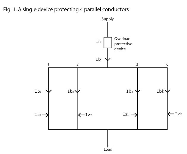
Fig. 1 shows a single device providing overload protection for four parallel conductors.
If for example, we need to calculate the design current for the fourth conductor, which we will call 'k', the formula in Regulation 433.1.1 for co-ordination between conductor and overload protective device (Ib ≤ In ≤ Iz) is replaced by:
Ibk ≤ In ≤ ∑ Izk
Where,
Ibk = the design current for conductor k
In = the rated current of the protective device
∑ Izk = the sum of the current-carrying capacities of the parallel conductors (ie. Iz1 + Iz2 + Iz3 + Izk)

Alternatively, overload protection can be provided in each parallel conductor as shown in Fig. 2.
In this case, the formula becomes:
Ibk ≤ Ink ≤ Izk
where,
Ink = the rated current of the protective device for conductor k
Izk = the continuous current-carrying capacity of conductor k
Item 2 in Appendix 10 of BS 7671 contains guidance on overload protection of conductors in parallel, including the considerations required where there is unequal current sharing between parallel conductors.
Fault protection
Regulation 434.4 states that where a single device is providing fault current protection, its operating characteristic must ensure that it operates in the event of a fault occurring at the most onerous position in one of the parallel conductors.
Where protection by a single device may not be effective, Regulation 434.4 contains measures which must be taken.

These measures include installing fault protective devices at the supply end of each parallel conductor where there are two conductors in parallel and installing fault protective devices at both the supply and load ends of each parallel conductor where there are more than two conductors in parallel (Fig. 3). It should be noted that a fault in one conductor at point x can be fed from both ends of a parallel conductor.
An alternative solution would be to install interlocked circuit-breakers at the supply end so that the operation of any one circuit-breaker causes all of them to operate (Fig. 4).

These arrangements are discussed in some detail in Item 3 in Appendix 10 of BS 7671.
Cable configurations
In large single-core cables, the reactive component of the impedance becomes significant and it is influenced by the configuration of the cables, which in turn, affects the current sharing. For single-core cables, only certain configurations give reasonable current sharing.
IET Guidance Note 6, Protection Against Overcurrent, gives examples of a number of recommended configurations for single-core cables run in parallel.
Other arrangements may provide acceptable current sharing but this should be checked.
Parallel conductors are often grouped and the rating factors for grouping would then apply.
Conclusion
This article should be regarded as a brief summary of a specialised subject. The requirements of BS 7671 should be studied carefully and any necessary guidance from cable manufacturers obtained before designing installations with parallel conductors.
Further reading
IET Guidance Note 6, Protection Against Overcurrent.
IET Electrical Installation Design Guide.
BS 7769 (BS IEC 60287) Electric cables. Calculation of the current rating.
As a NAPIT Registered Installer, you can access a wealth of technical information, guidance and advice.
If you would like more information on joining a NAPIT scheme, visit www.napit.org.uk or call 0345 543 0330